| By Maureen Albertson www.mysticparts.com ©Mystic Reel Parts LLC Questions? |
Penn SSV3500 Spinnfisher V Repair Walk-Through
Go here https://www.mysticparts.com/PennParts/Spinning.aspx#SS5thGen to order parts and access the schematics for the reels. This photo guide of the can be used as a reference for working on the slightly larger SSV4500 to SSV6500 reels as well.
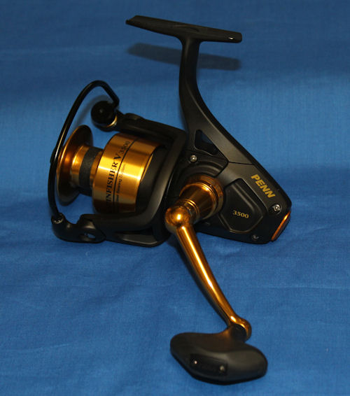
Assembly guide for the SSV3500 Spinfisher V series (with design change notes). As always, reference the schematic for the specific SSV model that you are working on. Example here is the SSV3500. I am using the key # from the drawing, which you match to the part numbers on page 2 of our online .pdf schematics.
CLICK ON ANY PHOTO TO VIEW LARGER SIZE
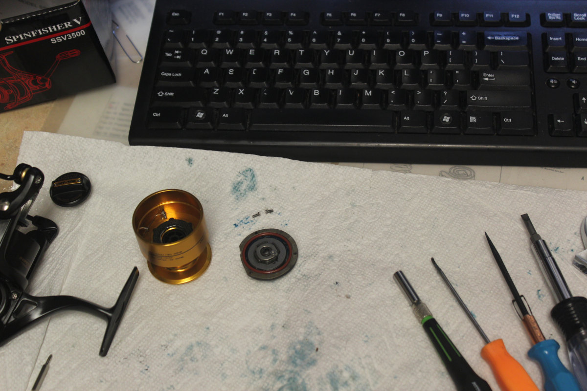
RECOMMENDED TOOLS:
- 1/4" and 1/8" Flat Head
- small adjustable wrench
- size PH000 Philips Head (for tiny screws)
- long skinny tweezers (for tiny screws)
- small bent tip bearing puller (for lifting/separating)
Quick jump to specific parts:
- Bail Wire, Line Roller, Bail Spring
- Housing & Main Gear
- Drag Washers
- Clicker
- Clutch (Anti-Reverse)
- Gear, Pinion *** Design change notes
Or just start reading from here:
Start as with most spinning reels, by accessing the main gearing in the housing, so that we can remove the spool shaft to get under the rotor at the pinion assembly. Remove the four #46 housing cover screws and remove the cover. You can see how the red #2L housing seal is positioned here.
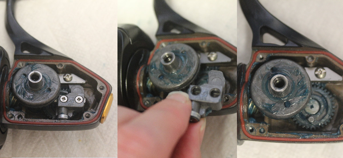
Turn the rotor until you can see both of the #44 block screws, then remove them. You can see that the pointed end of the #43 crosswind block sets into the track created by the #43A slider guide. When reinstalling these parts, make sure the #231 crosswind gear is positioned with the pin as shown, so that you can put the block into the track and onto that pin on the gear.
THIS IS WHERE YOU HAVE TO USE THE 000 MICRO PHILIPS HEAD! Take your time so that you don't strip out the screws.
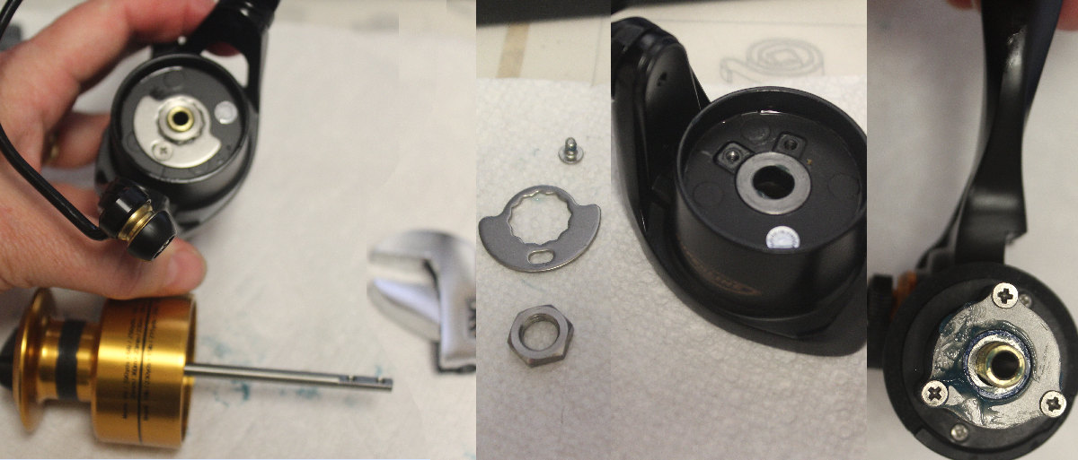
Slide the spool/shaft assembly out and set it aside. Remove the #38A screw, #95B locking plate and #38 rotor nut to remove the rotor from the housing and access the parts underneath. You can leave the #38D rotor washer on the rotor. Underneath, remove the three #28S rotor brake screws to take off the #21 pinion bearing retainer and access the pinion bearing assembly underneath.
Pinion Assembly
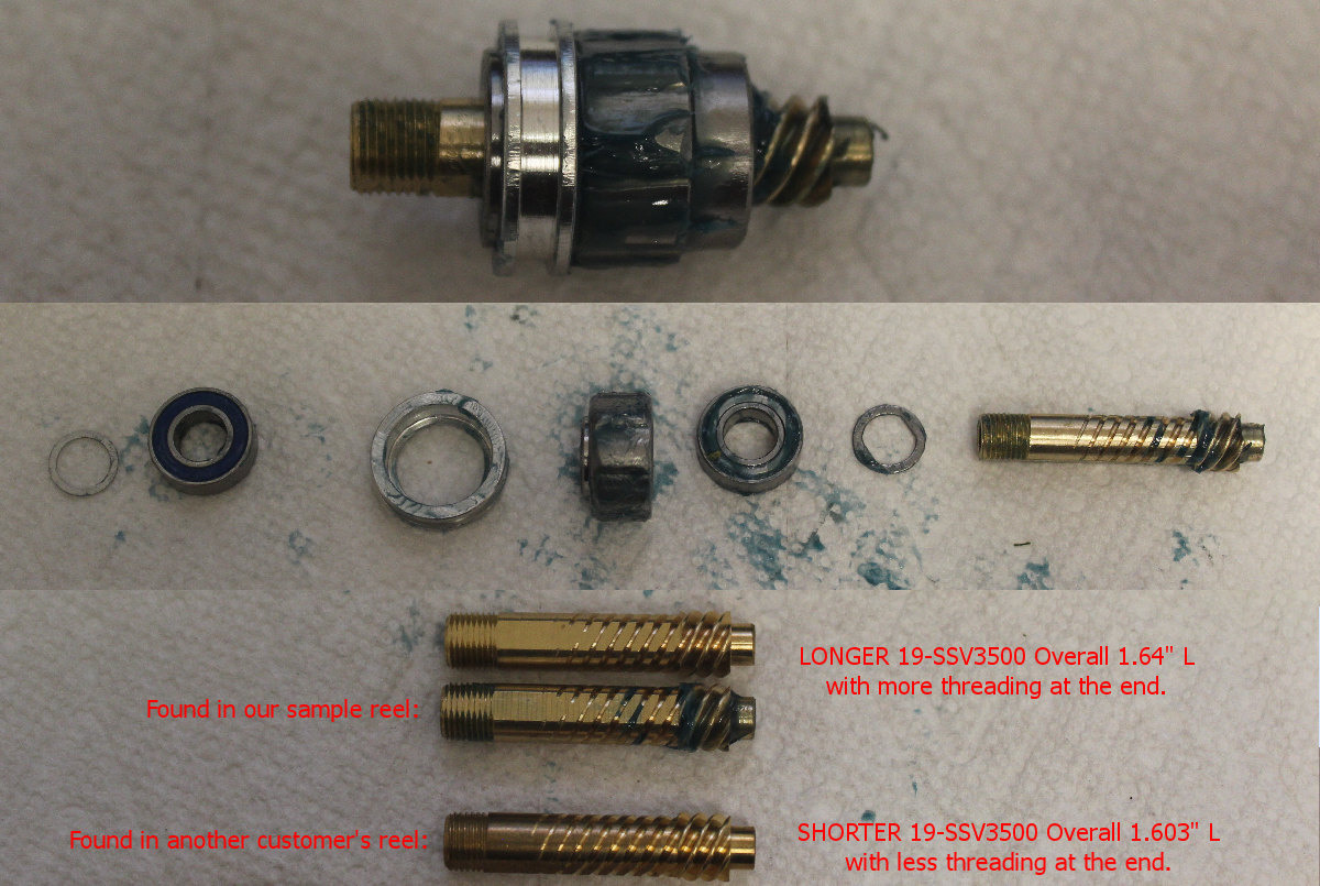
Once the #21 retainer is off, you can slide the entire pinion assembly out in one piece. Pay attention to the order and direction of the parts. Rounded end of the #98 clutch goes towards the spool side of the reel. There may be more shims in there than are shown on the diagram..if so, keep them in the position you found them in.
DESIGN CHANGE?
Here is where we get to address an issue that has been found in the SSV3500 reel. Earlier run? Has a slightly shorter pivot with less on the threaded end. Overall length of that one is 1.603"
Later run and corresponding later order of parts, has a slightly longer version of the #19-SSV3500 gear that is 1.643" overall..having about 2-3 more threads on the threaded end.
Trying to install the longer pinion in a reel that had the shorter one resulted in a tapping sound as the shaft appears to be bottoming out against the extra length. This implies that another part, like the rotor may have also changed thickness. NOTE: I'm still investigating this problem and will consult with Penn about it. Meanwhile, we currently have both pinion types available and I will label the inventory accordingly. ~MizMo
Clutch/Anti-Reverse
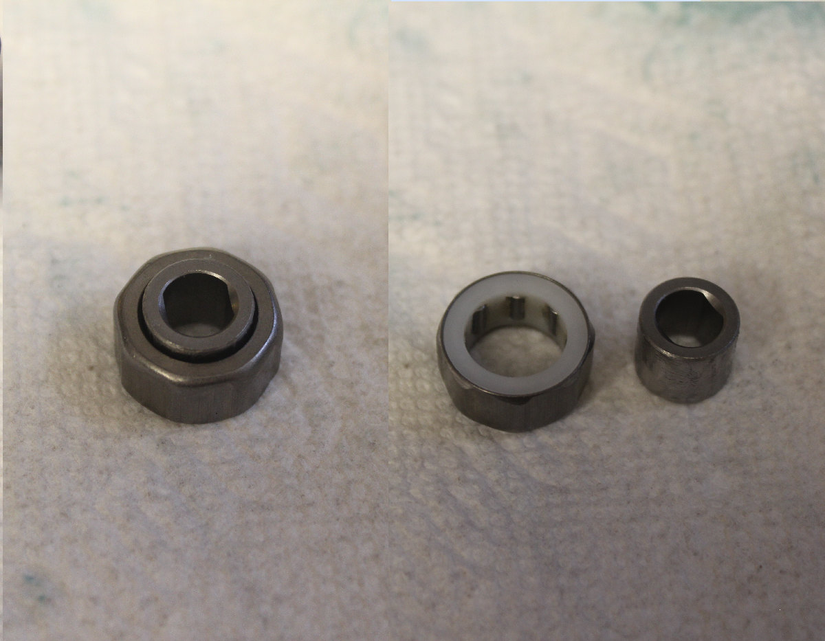
As stated before, the rounded end of the #98 clutch bearing should be pointing towards the spool. The flatter side with the white bushing visible should be facing the housing. It is recommended that you do NOT grease the inside of the clutch bearing or the a/r may slip!
Bail Wire, Spring and Line Roller Assembly
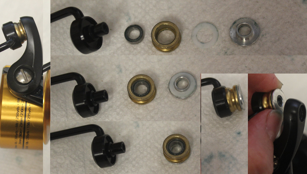
A quick series of shots, right to left. A breakdown of the parts as they came off the bail wire and are put together to go back onto it.
#35A bearing sets into #35 roller. The white 132A washer sits onto the #132 metal roller washer. Then the roller with the ball bearing in it sets onto the roller washer. Place onto the bail wire seat then reattach assembly
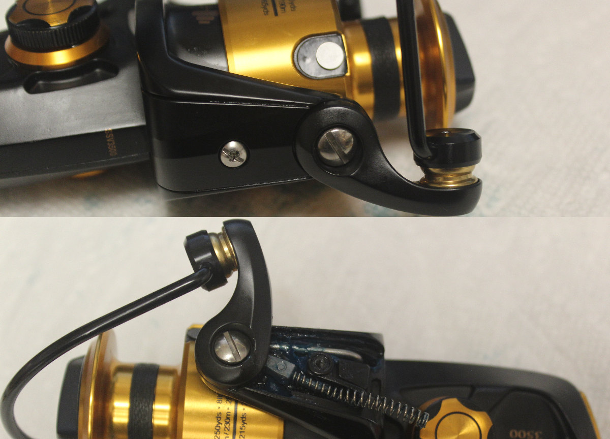
Bail Spring: Be forwarned, once you undo the # screw to release the #27A rotor cover, the spring will jump!
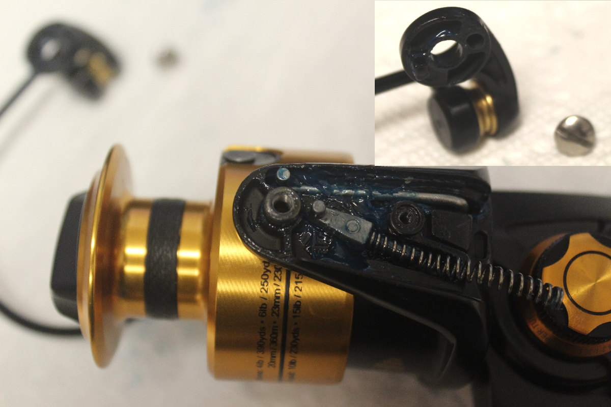
The tip of the #34C pivot arm goes into the little round hole in the #34 bail arm...make sure that the hole is still round as bail arms can wear into an oblong. The tip of the #28 will ride in one of the long grooves, see postioning of the arm in the phot.
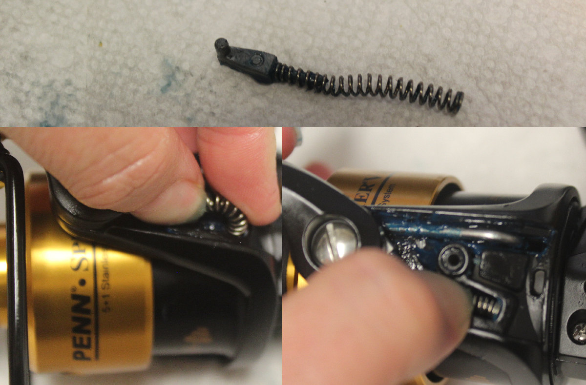
The #32 bail spring is hard to reinstall because the long spring is somewhat overpowering. Slip it back onto the pivot arm and bend it into a U shape with the end tucked inside the rotor. With your finger closer to that end, press the spring down into position...DO NOT LET GO!
Still holding the #32 spring in place with your finger, slide the #23A cover into place and secure it with the #22 screw.
Drag Washers - Top of the spool
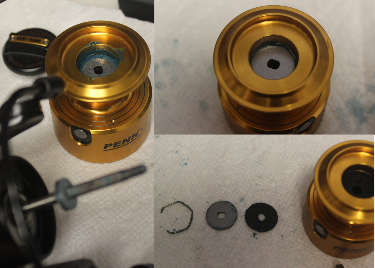
With a finger lying across the opening in the top of the spool to keep it from flying out, pop the #51 ring out with a flat head screw driver. Check the two washers #56T friction and #57T metal underneath for wear or damage, replacing as needed.
Order of placement: HT100 in first, then metal on top and ring to secure them in place.
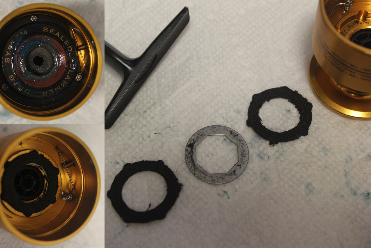
Drag Washers - Underneath the spool
THIS IS WHERE YOU HAVE TO USE THE 000 MICRO PHILIPS HEAD! Take your time so that you don't strip out the screws.
Remove the #22A screws securing the #47C drag cover. Note that one of the screws goes through the loop in the end of the #47F line clip retainer and then into the 47C cover.
If the clicker is working fine, do not disassemble it. If something needs replacement, see the Clicker Assembly and Seal. Set this unit aside.
Once the cover is off, you can check the drag stack inside and replace as needed.
Order of placement as shown.
Left to right, top to bottom assembly steps for putting underside drag assembly back in place.
USE TWEEZERS TO HELP PLACE THE TINY SCREWS!
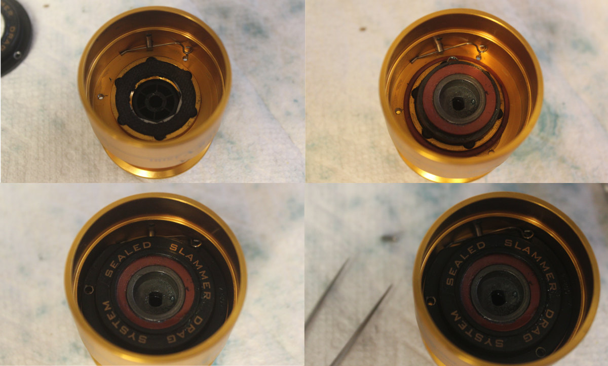
I first tucked the #48S seal into place inside the spool. Next, I found that it was easier to lay the clicker assembly with the 47S seal directly on top of the drag washers in the spool before placing the #47C cover.
SPOOL ASSEMBLY:
To line up the keyed washers, put the spool on upside down and wiggle until it can drop down all the way through, then take it off and set it on in the correct position and resecure with the #52 drag knob.
>Clicker Assembly and Seal
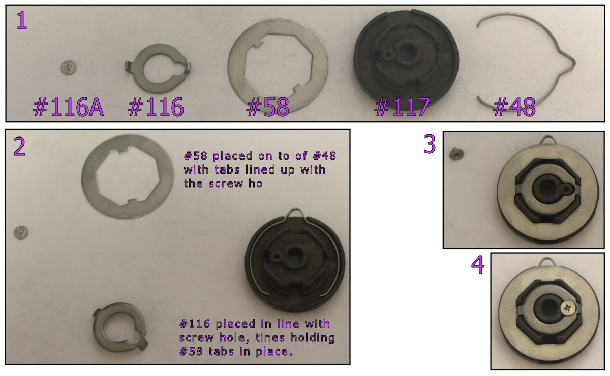
Position parts as shown in photo layout above.
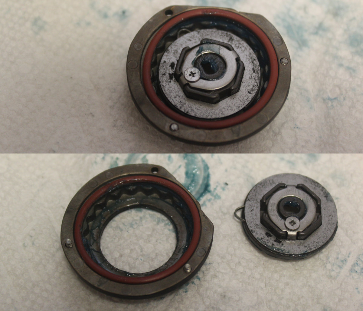
You can see the placement of the Clicker Assembly and the #48S seal.
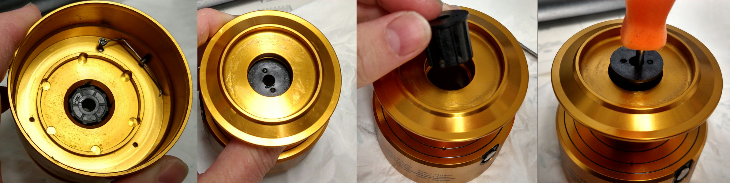
Removing the spool bushing is done after taking off top and bottom drag washer systems. Push the bushing up from the underside of the spool using level pressure with a screw driver handle. Reinstall it from the top as shown. Center the bushing and push straight in using screw driver handle with level pressure until it stops.
Order parts online for the reel(s):
https://www.mysticparts.com/PennParts/Spinning.aspx#SS5thGen
0 Comments