 Copyright © Alan Tani Reprinted with permission of the author.
Pull up the schematic and follow along with me.
30SW Schematic and you can order parts here: https://www.mysticparts.com/PennParts/Penn30SW.aspx
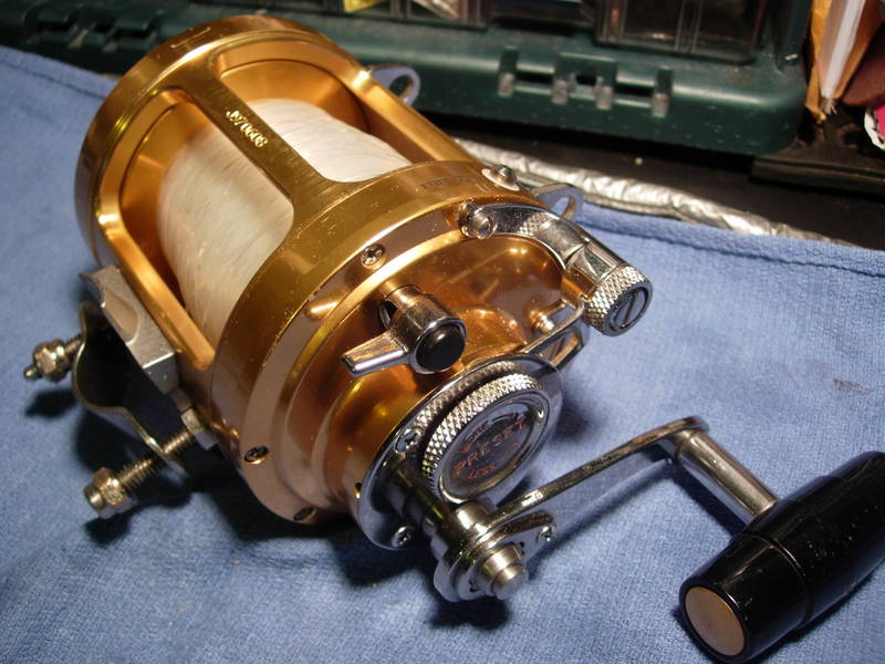
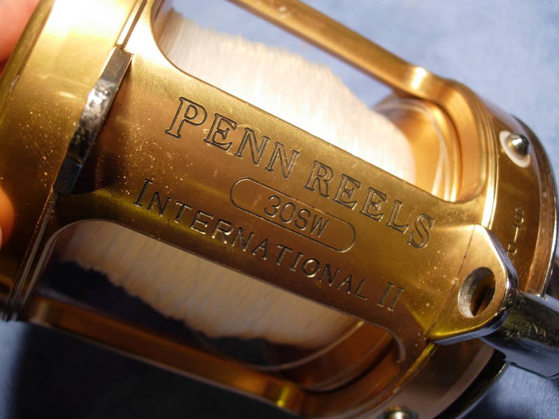
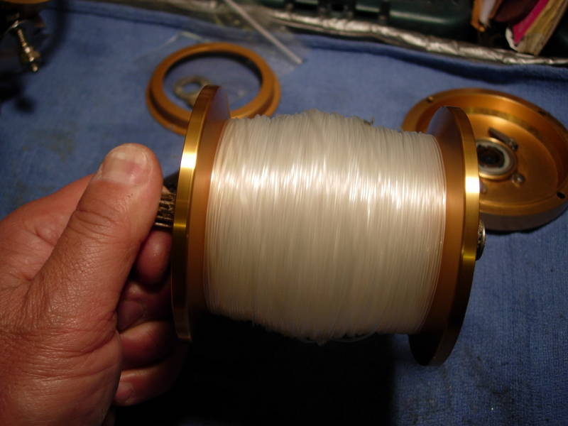
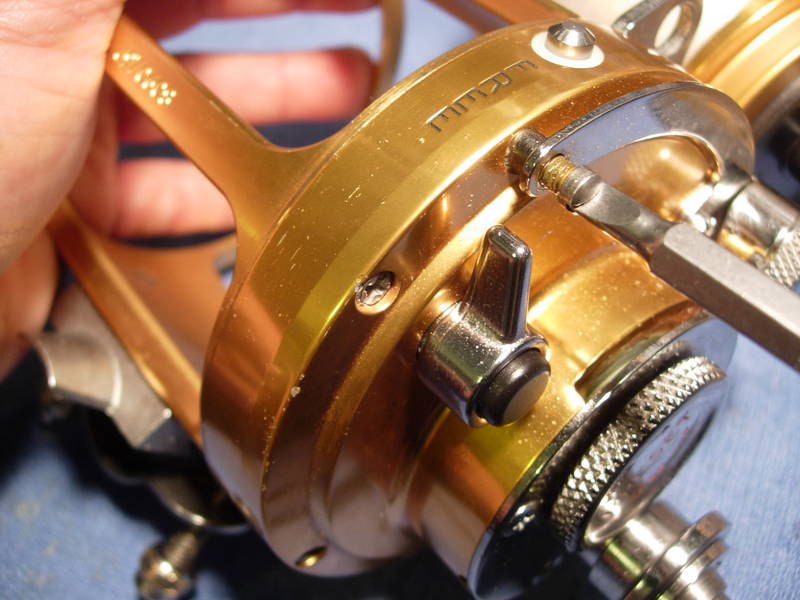
Here's your reel, a classic Penn 30 wide two speed international.
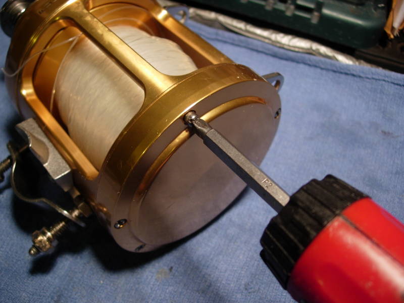
What we're going to do is grease all of the screw holes, grease the drag washer, cut a bearing sleeve, service the bearings and install a custom handle. Let's start with the left side plate assembly(key #27). Back out all of the left side plate screws (key #'s 31a and 38a).
Remove the left side plate assembly and check for the dogs (key #15) and the left side plate bearing (key #55). You will rarely find a thrust washer (no key #) in some models, while it is missing in others.
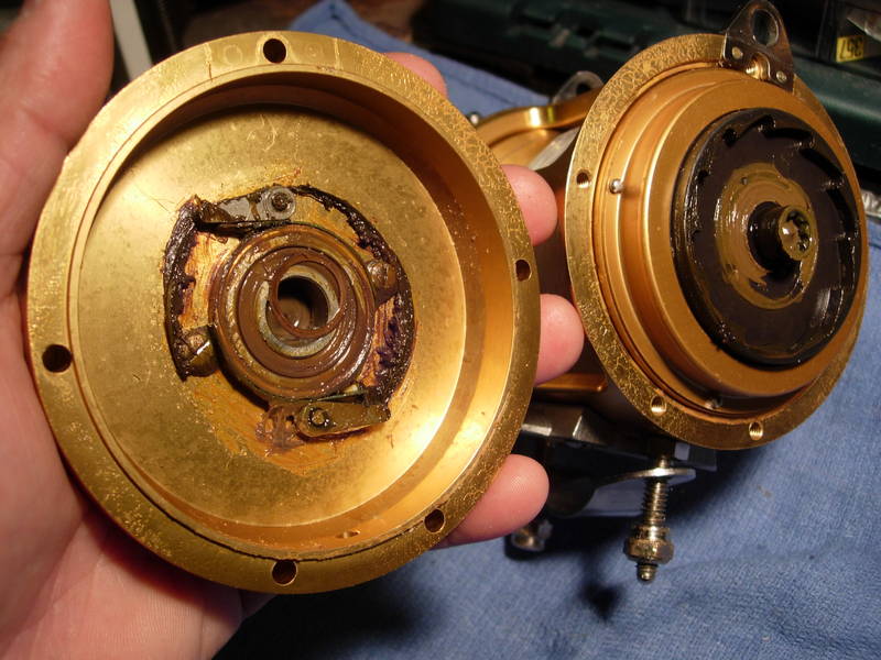
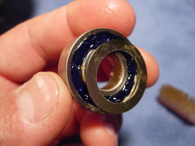
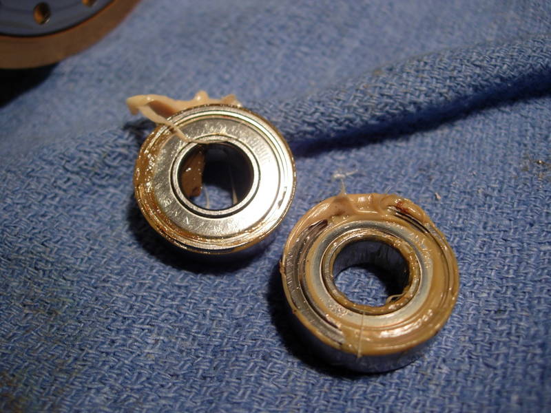
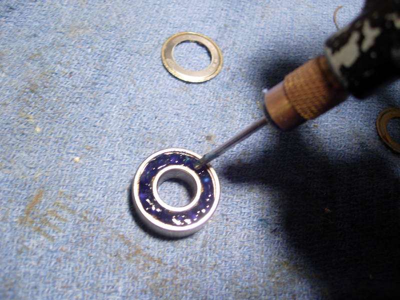
Clean everything up a little and pull the left side plate bearing (key #55). Since this bearing does not affect free spool, we are going to extend its life by packing it with grease.
Review the "bearings" post if you are unfamiliar with the procedure, remove the shields and hand pack the bearing with grease.
Replace the bearing shield if it is possible.
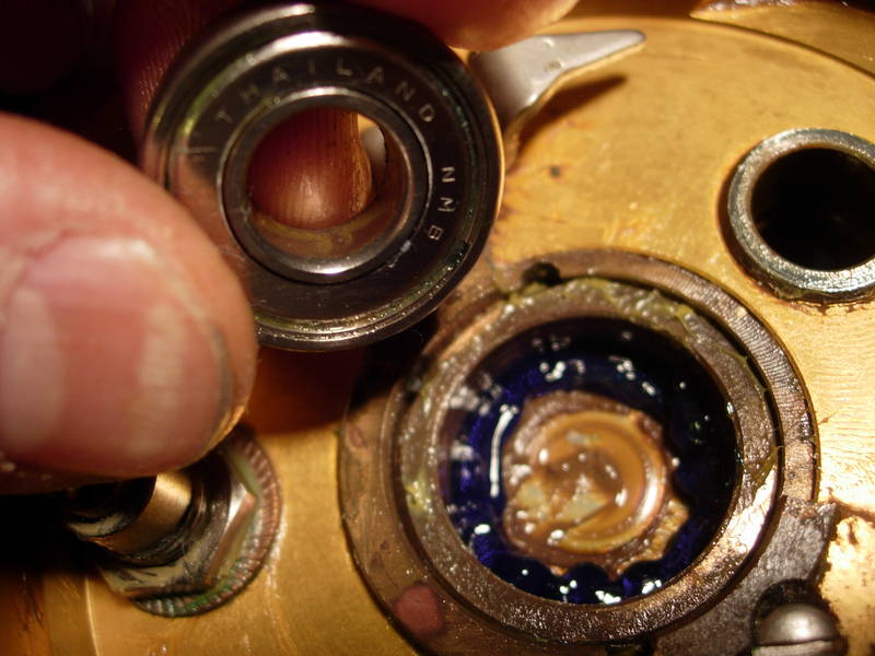
Add a little grease to the bearing cup.
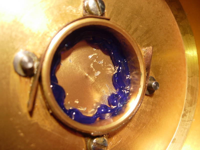
Carefully press the bearing (key #55) back into the left side plate (key #27). Replace the thrust washer (no key #) with a little grease to hold it in place. Replace with dogs (key #15) with a little grease to hold them in place as well.
Ok, the left side plate assembly is done. That takes care of the first bearing. Set it aside and let's move on.
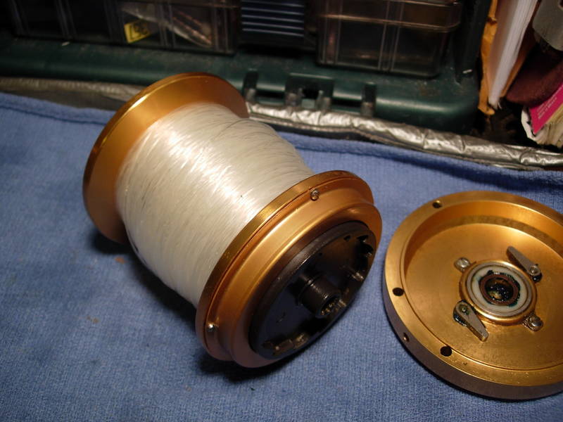
Next is the spool assembly. Here we are going to service two more bearings, cut a bearing sleeve, grease the drag washer, change the orientation of the belleville pressure washers (if needed) and grease the screws that hold down the drag cover.
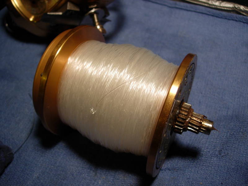
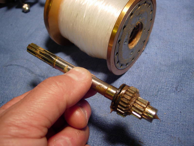
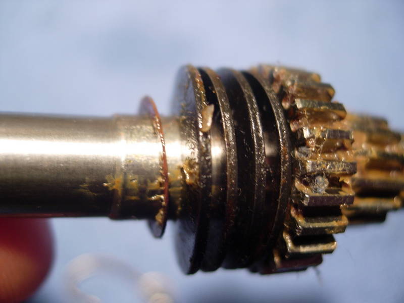
The pinion gear and spool shaft are a single unit (key #13) and simply pulls out.
What comes with it are typically a set of four belleville disc clutch springs (key #18). These belleville's are oriented in a softer "()()" configuration which gives you a lower drag range. You also may or may not have an additional thrust washer (no key #) located toward the inside of the belleville's.
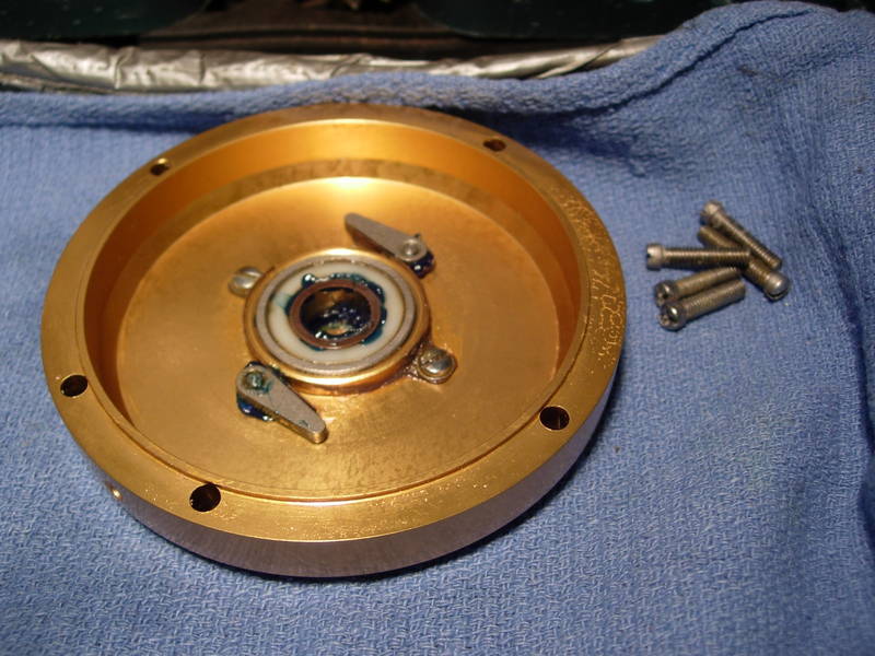
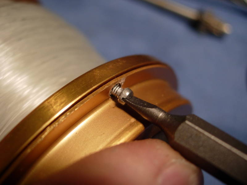
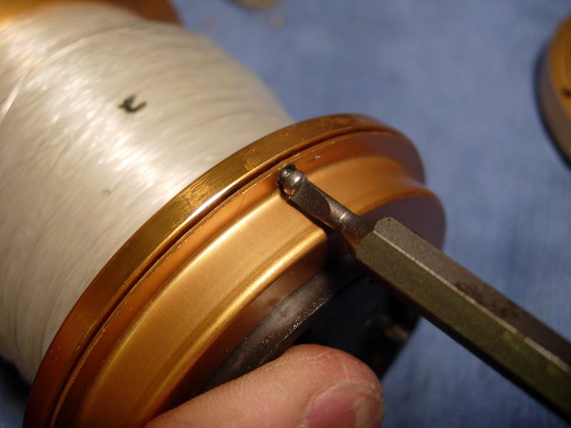
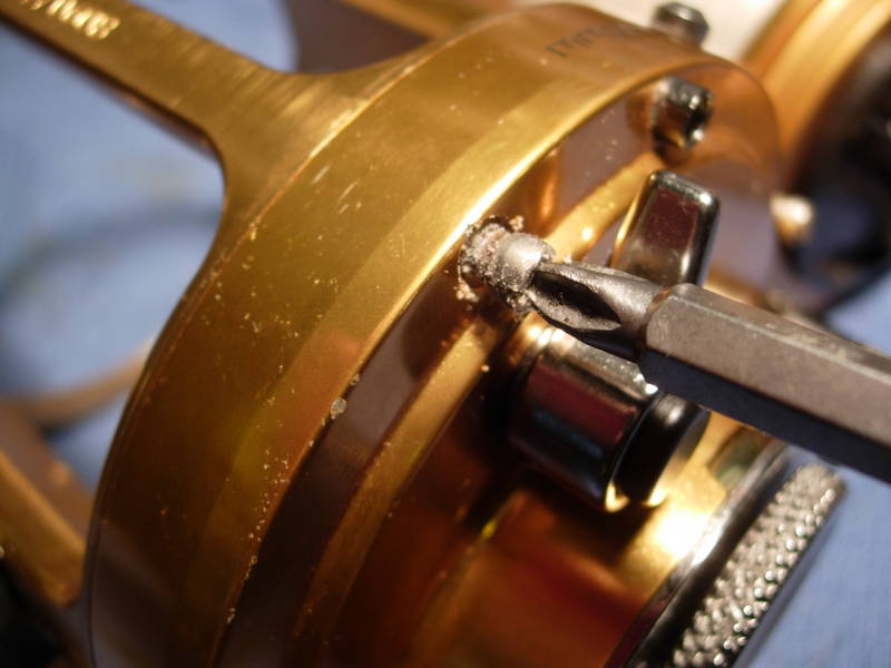
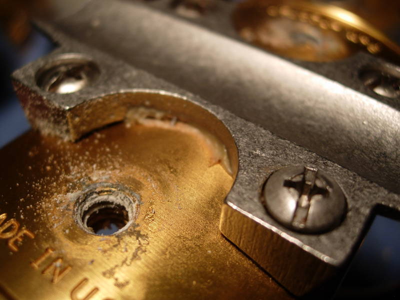
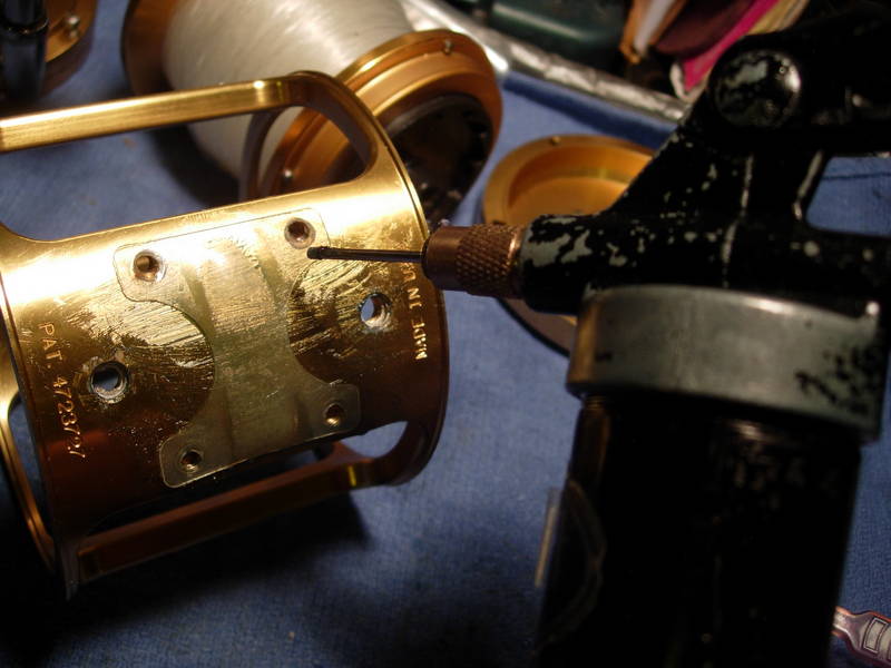
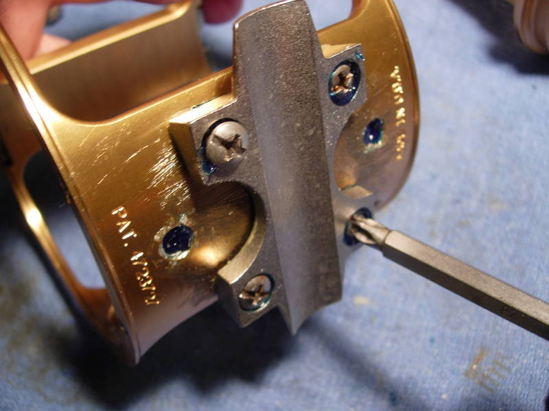
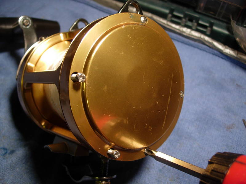
To remove the drag cover (key #156), let's back out the four drag cover screws (key #123). Note the corrosion seen in this photo. I will occasionally come across screws that are so badly corroded that these screws will snap off at the base. If that happens, don't worry. You have a perfectly reasonable option of simply leaving the drag cover off. Another reel has a similar design. It is called an Avet.
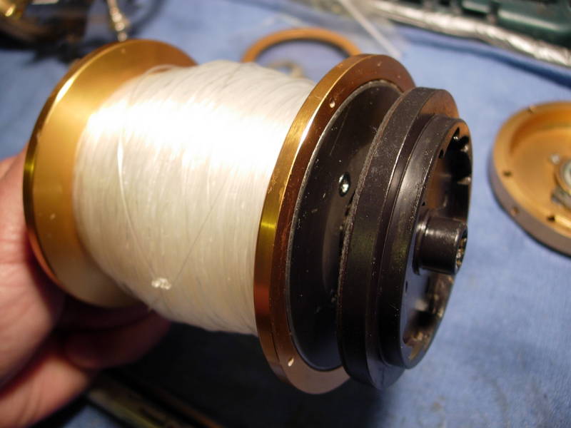
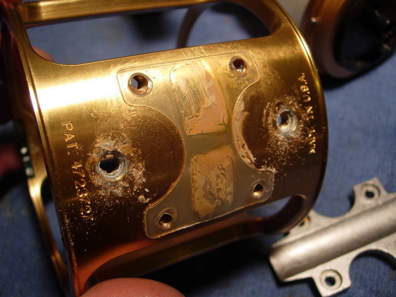
Now that the cover is off, everything will come apart. (sorry, you will see this photo twice.) Note that this spool assembly is missing a gasket (key #156a). It's not a problem.
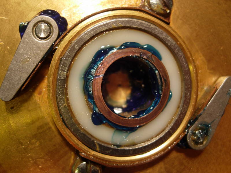
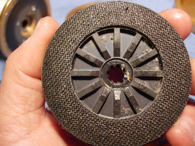
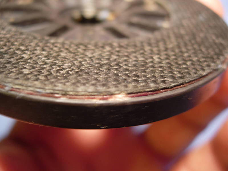
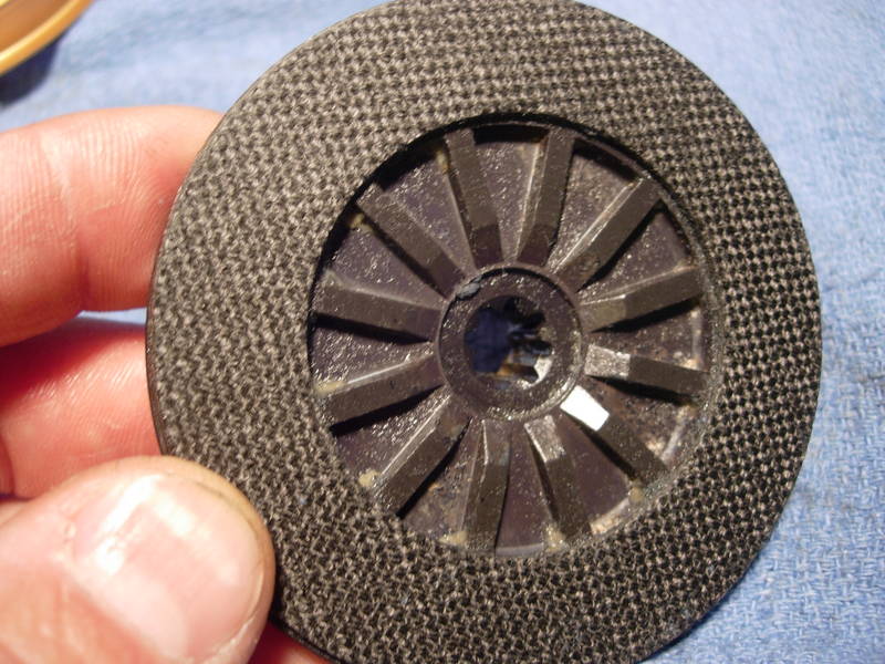
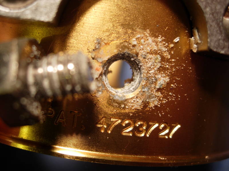
Let's take a look at the drive plate. It is very simply a Penn ht-100 carbon fiber drag washer glued to a cast aluminum pressure plate. What we are looking for is evidence of water intrusion. If salt water seeps in between the drag washer and the aluminum, it will eventually form a bubble of corrosion. This high spot is what sticks and is basically the reason that these dry drag washers fail. You can see evidence of salt water intrusion along the outer edges of the drag washer, from the 3 o'clock position to the 10 o'clock position. Salt appears to have been deposited onto the drag washers surface but has not reached the aluminum to cause corrosion.
Checking the edge of the drag washer, you can see a small spot of corrosion and some slight lifting of the drag washer off the surface of the aluminum backing plate. Jumping ahead a little, I will tell you now that this is minimal and will not affect the smoothness of the drag washer. Once it's greased, that is.
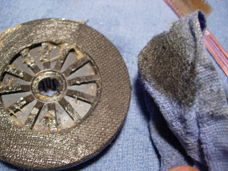
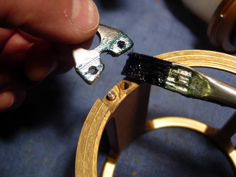
Slap a nice, thick, juicy coat of Cal's grease on the carbon fiber, making sure you get the inside and outside edges.
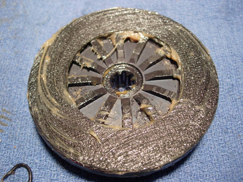
Take a clean rag and carefully rub away all of the excess grease.
This is what it will look like when you are done. This is a carbon fiber drag washer that is impregnated with pure teflon grease.
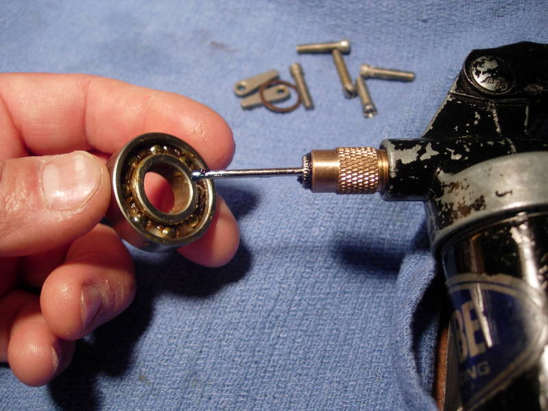
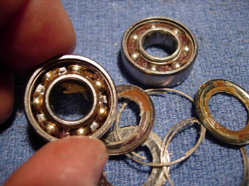
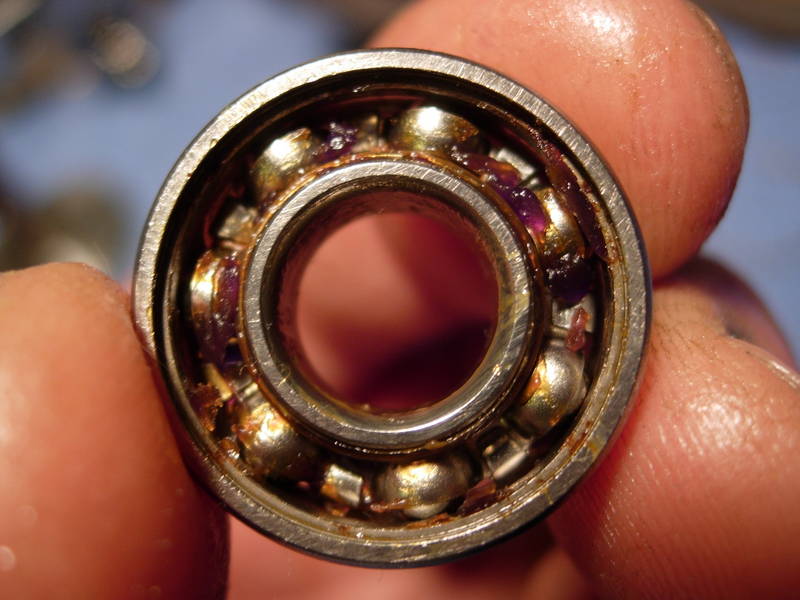
Now for the spool bearings (key #20). The dimensions are 0.5 x 1.125 x 0.312 and they should pop right out. If they do not, the stop and take a hard look at them before you start pounding. There are no retaining rings holding in the left spool bearing. Give it a light tap. If you have to pound to get this one out, plan on having to replace it because the pounding will ruin the bearing. Some models actually have a retaining ring on the right side. To remove the retaining ring, you must remove the ratchet plate (key #81) first.
Open up these bearings, clean out all the grease with carb cleaner and compressed air, lube them up with corrosion x and set them aside. Let's leave them unshielded.
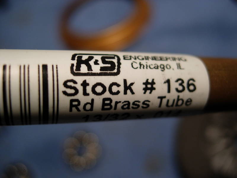
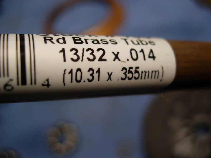
Something new that I've been doing, starting in the summer of 2008, is cutting bearing sleeves. I've been buying thin walled brass tubing from the local hobby shop and cutting them down to fit in-between the bearings. The increased free spool has been dramatic. Here's the tubing needed for this reel.
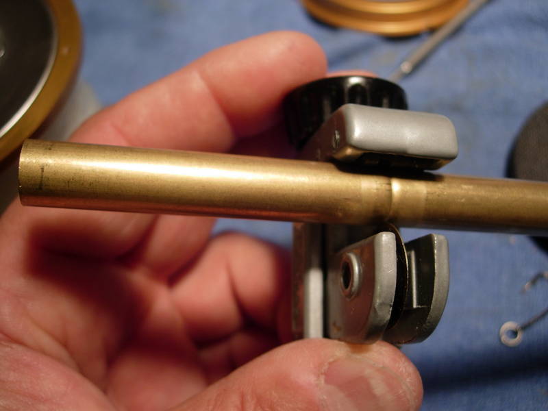
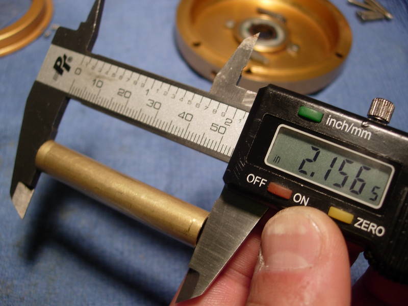
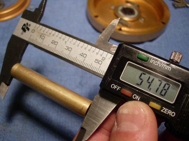
The whole process is relatively simple. I get a quick measurement of the length needed and cut it with a tubing cutter.
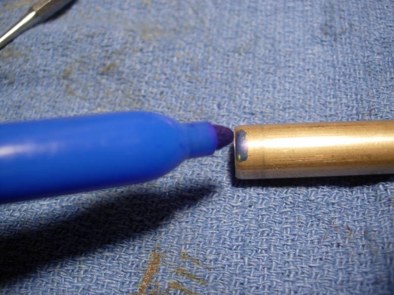
Then I re-measure the length and mark the amount of metal that needs to come off
.
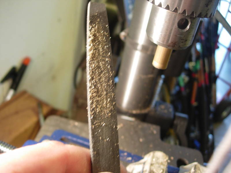
The sleeve is then placed in the chuck of the drill press. Even a hand held drill with a half inch chuck would work.
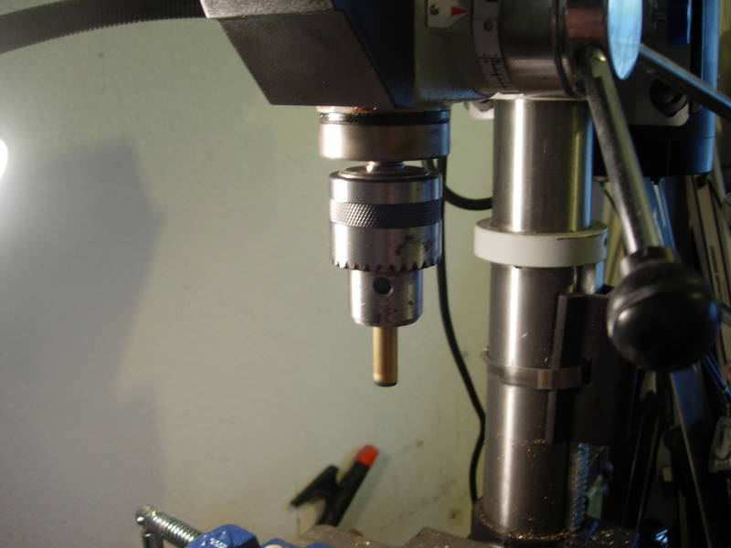
A standard mill bastard file will shave off 5 to 10 thousandths of an inch with every stroke, depending on how sharp the file is and how hard you lean on it. After a few tries, you will get the feel for it. Plan on having to do this a few times before you get it right.
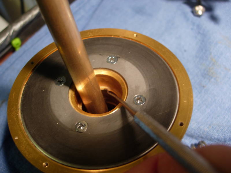
Ideally, you want zero load and zero endplay. Actually, if you cut it too short, you may as well start over because the bearing sleeve will not work at all. If it's too long, the spool can move around while in free and you may note that the spool stops when you roll it to the right. You want to be right on the money, or not more than 10 thousandths long. This one was perfect. With just the bearings and sleeve in place, you should be able to push in on one bearing and feel just the slightest amount of pressure on the other. It you can push in on one bearing and actually move the other bearing completely, the sleeve is way too long.
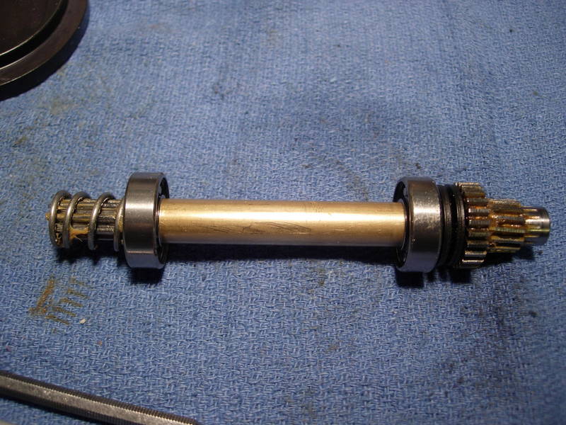
Here is what the spool shaft assembly looks like with the bearing sleeve in place.
To check the function of the bearings and bearing sleeve, first place the spool shaft assembly in the spool and give it a spin. You should get about 30 seconds of free spool.
Now place the drive plate (key #117) on, press only half way to put pressure on the left side bearing spring (key #41) and spin it again. If you get the same amount of free spool, then you know that there is no axial load on the bearings and it works. Again, make sure the bearing sleeve is not too long.
Grease the screw holes in the left side of the spool (key #29).
Install the drag cover (key #156) and the four drag cover screws (key # 123)
.
The drag washer is now grease and the bearings are now open, lubed, and sleeved. Three bearings serviced, one more to go. Set the spool next to the left side plate and let's move on.
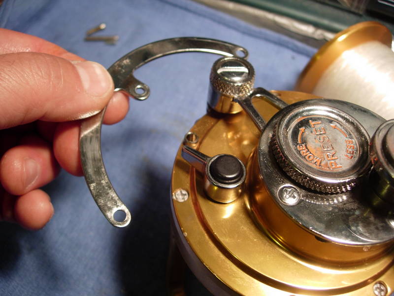
Let's start on the right side plate assembly (key #1). Remove the screws (key #'s 31, 32 and 38b) for the quadrant (key #2). Note that all of these screws are different lengths.
Set the quadrant and the screws aside. Don't forget the two quadrant spacer bushing (key #157).
Remove the remaining right side plate screws (key #'s 31a and 38a). Note that the long one goes at the 12 o'clock position.
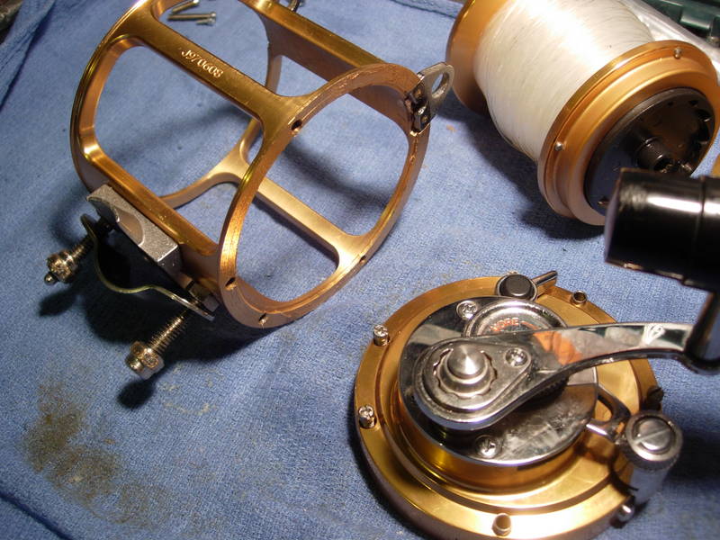
Ok, it's apart. Set the right side plate assembly aside. We will service the frame first.
This will be simple. First, put a little grease on the harness lugs.
Next, let's add a little grease to all of the side plate screw holes. Just a small bead is all that is necessary.
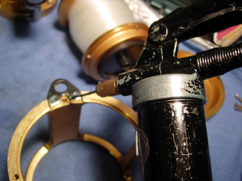
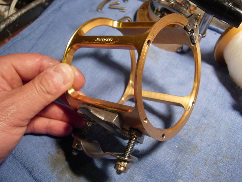
Remove the rod clamp assembly, including the acorn nuts (key #152a), the rod clamp (key #33), and the clamp screws (key #34).
A note of caution. Aluminum around the clamp screws will corrode quickly. It is common to have them corroded so badly that the screws will snap if you try to horse them off. Drilling them out and re-tapping the hole is a nightmare. If you have one of these reels, check the clamp screws now and grease them if you can. Otherwise, just leave them be.
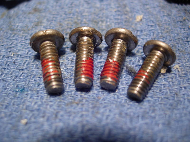
Remove the four stand screws (key #63). They will need grease as well. Note that one of these loosened up already. So much for loctite.
Several you have voiced concern over my recommendation that these screws should be greased and not just coated with loctite. I know your concerns are genuine and I thank you. I have decided, however, to continue with grease, and to carefully torque these screws down. Owners are advised to check the stands periodically. I believe that preventing corrosion takes priority.
Remove the stand (key #30) and optional the stand gasket (key #264).
Grease all of the screw holes.
Install the stand gasket (key #264), the stand (key #30) and the four stand screws (key #63). Lean on those screws a little and make sure they are good and tight!!!!!!!
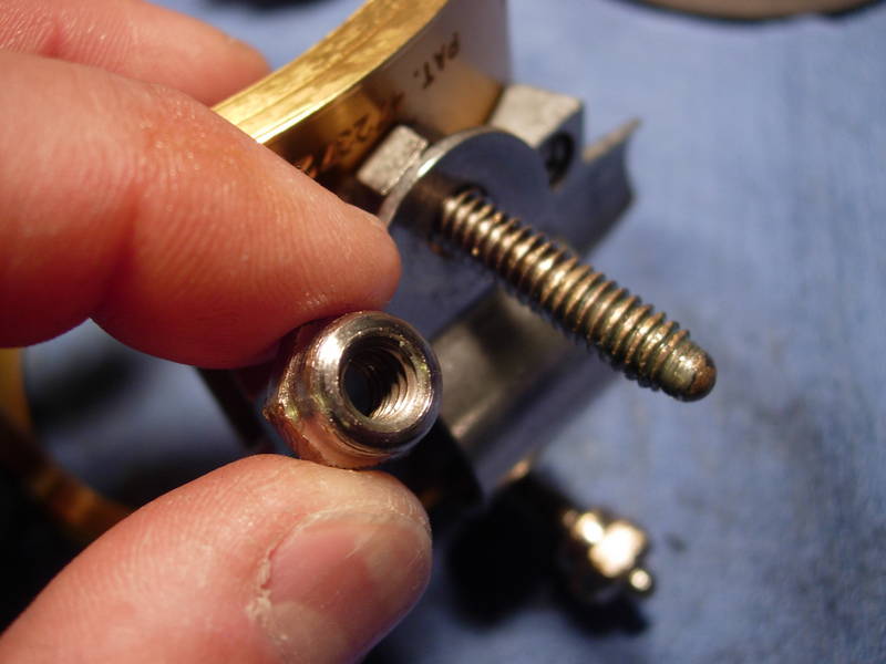
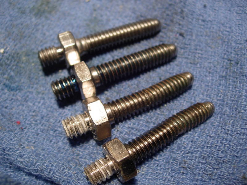
The clamp screws (key #34) are chrome over fairly soft brass, not stainless steel.
Install the clamp screws (key #34), the rod clamp (key #33), and the acorn nuts (key #152a). We're done with the frame. Set it aside with the left side plate and spool. We still have one more bearing to service.
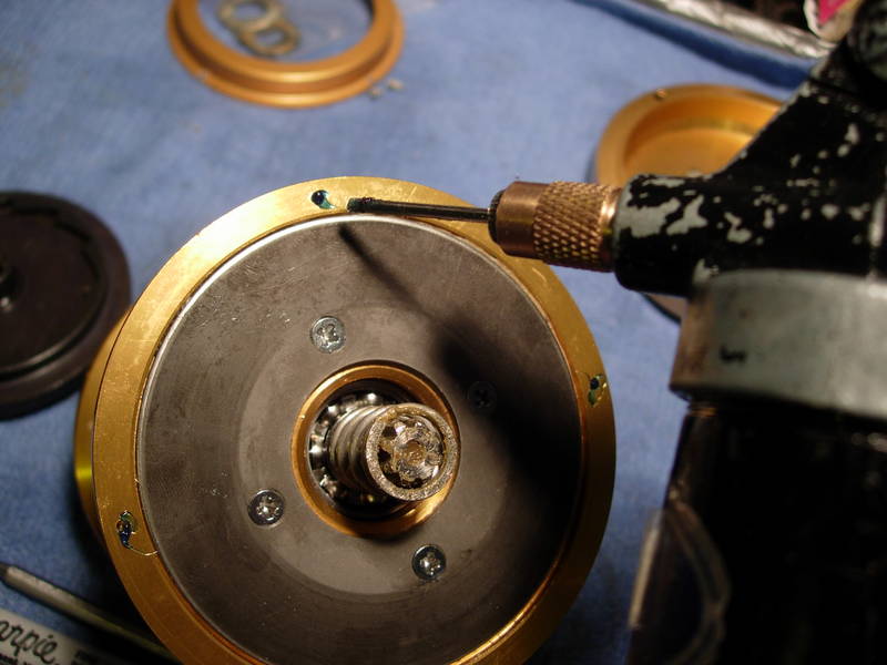
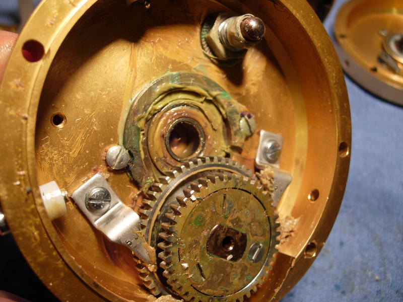
There is the last bearing. This is the part that was omitted from the original Penn 30s rebuild post. This right main side plate bearing (key #20) is the most problematic in all of the lever drag reels. It bears the greatest load and is always the first to corrode. Its dimensions are the same as the spool bearings, 0.50 x 1.125 x 0.312. We'll have to remove the handle and the main gear to get to it.
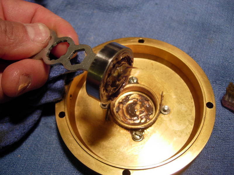
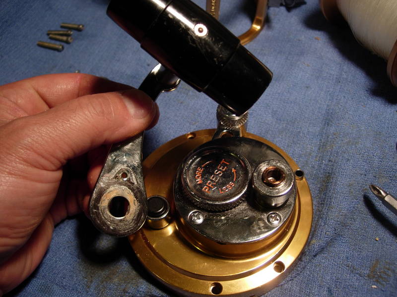
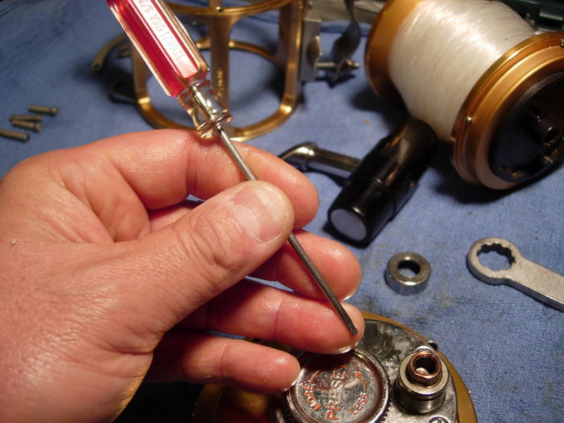
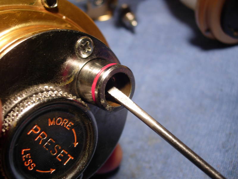
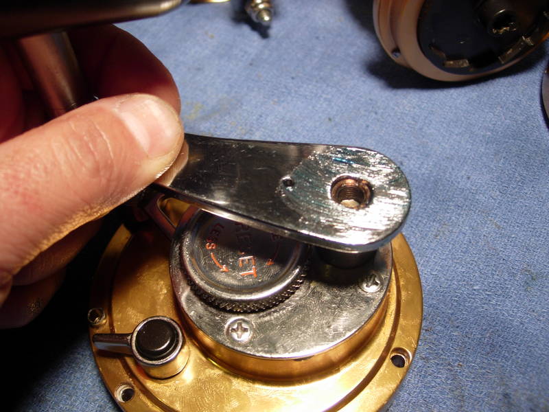
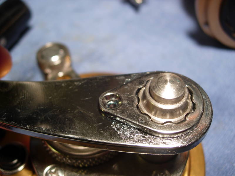
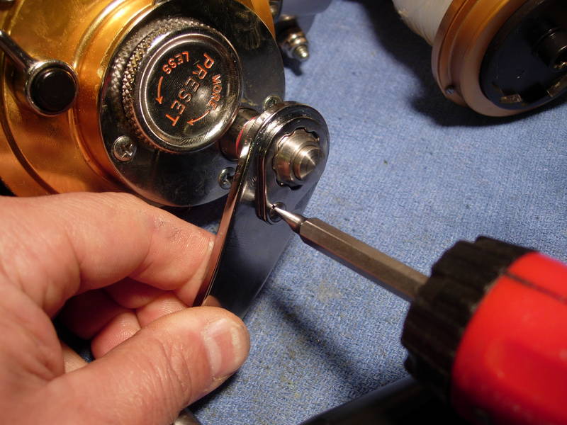
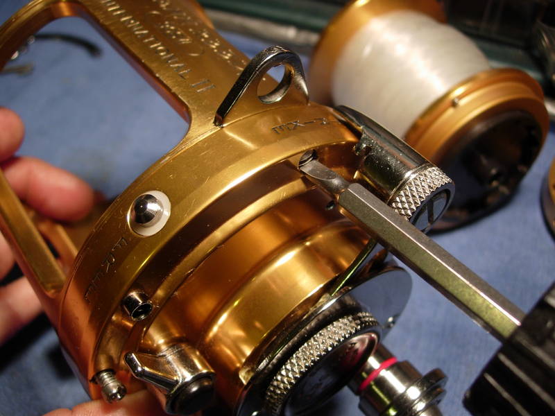
First, remove the handle lock screw (key #110) and the handle locking plate (key #110a).
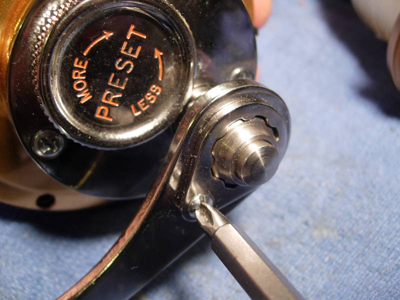
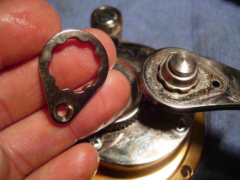
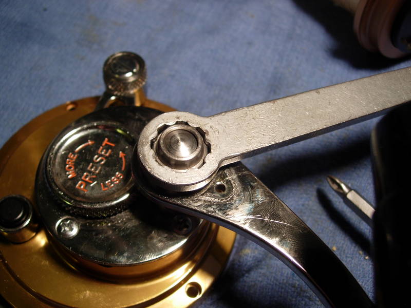
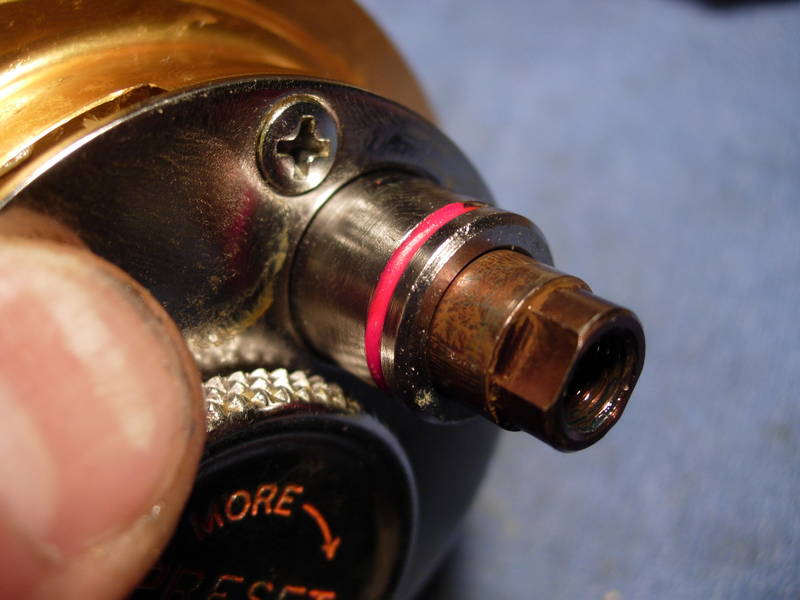
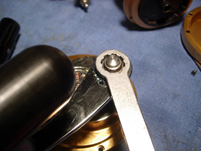
Remove the handle screw assembly as a unit, including the plunger cap (key #172, the handle screw (key #23), the retaining ring (key #69b). A standard Penn wrench will work well here.
Remove the handle assembly (key #24).
Remove the drive shaft shield (key #50).
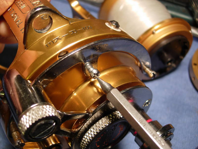
To remove the main gear assembly, we must first loosen the hold down screws (key #63a). It is not necessary to remove the gear retainers (key #173). They only need to be loosened.
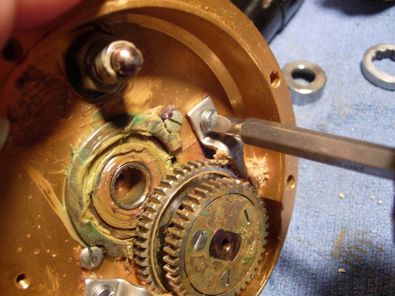
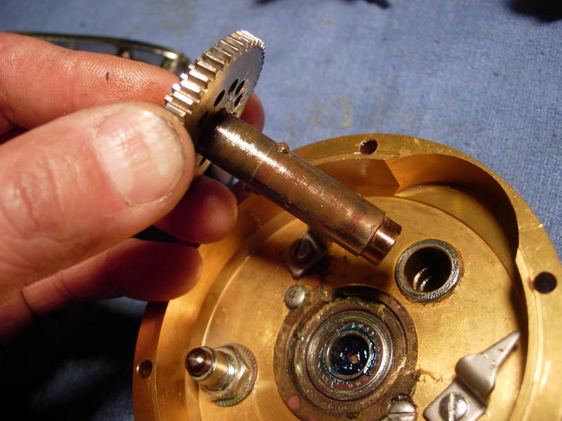
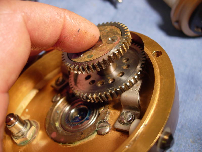
The main gear assembly is made up of many parts. To remove it, simply push down on the plunger pin (key #171) and the main gear assembly will come out as a unit.
Inspect the main gear assembly and find the two plunger pins (key #172a). Note the orientation. There is a flat side and a rounded side. The rounded side faces out. Carefully remove the plunger pins, add a bead of grease to the holes and replace the plunger pins, rounded side out.
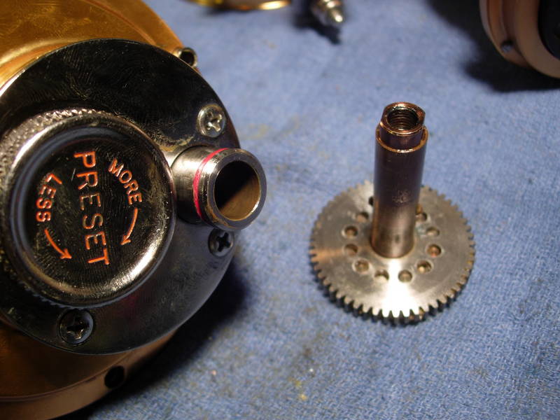
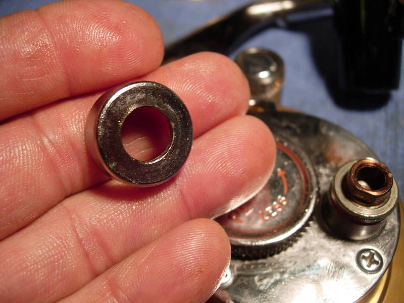
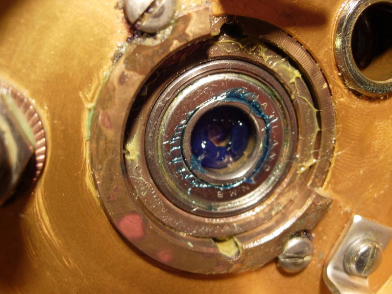
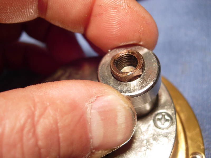
Remove the right main side plate bearing (key #20).
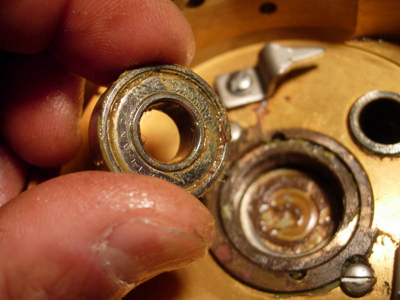
If it's in good shape, let's crack it open, pack it with grease, put the shields back on and re-install it back into the side plate. Otherwise, let's get a new one. You will know if the bearing is bad because it will feel crunchy when you turn it with your fingers. Before you even opened the reel up, you should have felt some grinding when you turned the handle, worse in gear, less in free.
To reinstall the main gear assembly, slide it in as far as it will go. It will stop when it reaches the plunger pins.
Push down hard against the main gear assembly with your left index finger.
Push down slightly against the plunger (key #171) until the plunger pins give.
The main gear assembly will pop right into place and lock in!!!!!!!!
Install the drive shaft shield (key #50).
Install the new custom handle (a $33 6/0 Kolekar grip and $17 Penn 50 arm).
Install the handle screw assembly (key #'s 172, 23 and 69b).
Install the handle locking plate (key #110a).
Install the handle lock screw (key #110).
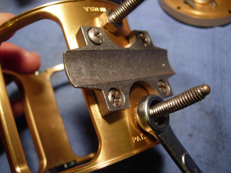
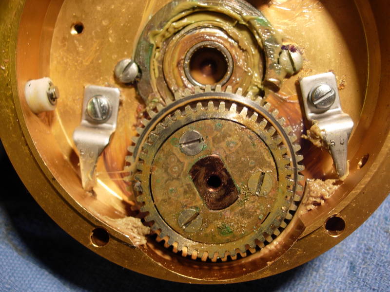
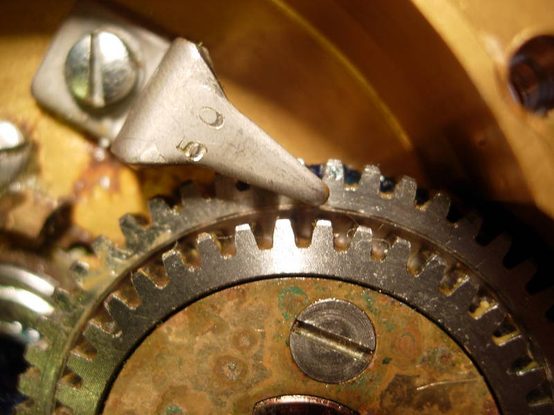
Position the gear retainers (key #173) so that the points of the gear retainers rest over center of the backbone of the high speed main gear. Tighten the hold down screws (key #63a).
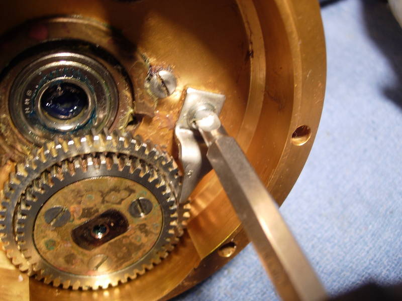
The point of the gear retainers (key #173) must be dead center. Do not allow the point to rest over the teeth of the high speed main gear to the outside and below, or to touch the teeth of the low speed main gear to the inside.
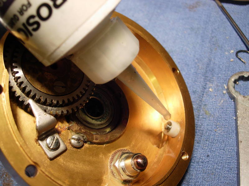
Take a moment to lube the inside and outsides of the locating pin assemblies (key #69). Disassemble the unit for proper lubrication if needed.
Ok, the right side plate assembly is done and it's time to get this reel back together an run it through its paces. First, let's get a little grease in the recessed side plate screw holes. I found some corrosion in there earlier.
Install the right side plate screws (key #'s 38a and 31a). Remember, the long one goes at the 12 o'clock position.
Install the quadrant (key #2) with the quadrant spacer bushings (key #157) and the three quadrant screws (key #31, 32, and 38b).
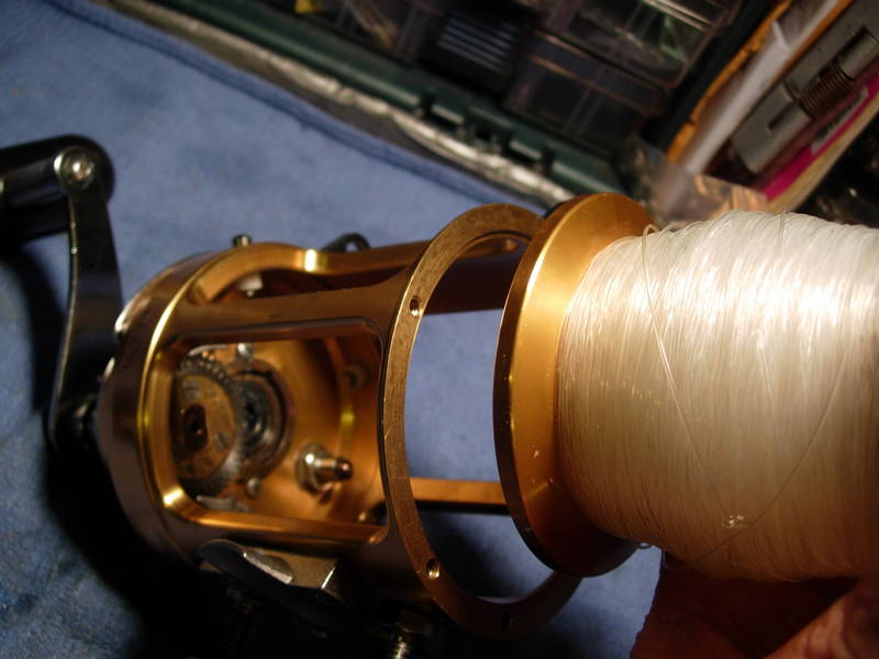
Install the spool assembly (key #29).
Install the left side plate assembly (key #27). Put a little grease in the recessed screw holes (remember the corrosion found on the right side?). Place the dogs (key #15) down position, resting against the dog springs (key #14). Let's make sure now that the lever on the right side is in the "free" position and that the preset knob is backed all the way counterclockwise. Now line up the left side plate and it should seat. If it does not, give the handle a slight crank. That should do it.
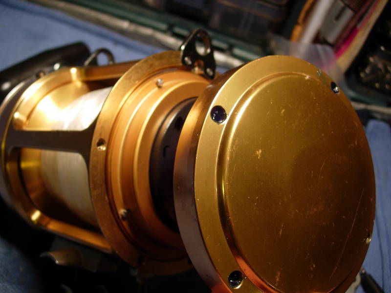
With the left side plate properly seated, the spool should spin freely. Check it first, then install the left side plate screws (key #31a and 38a). The long screw goes in at the 12 o'clock position.
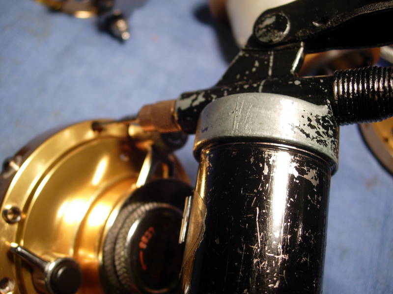
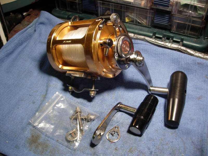
There you have it! A blue printed Penn 30sw with custom 6/0 Kolekar handle grip on a longer 50 international handle arm.
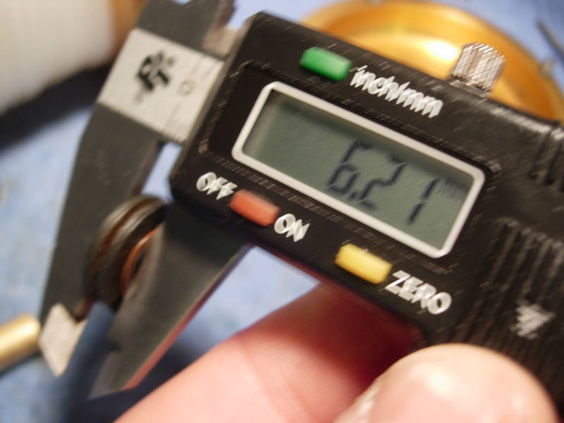
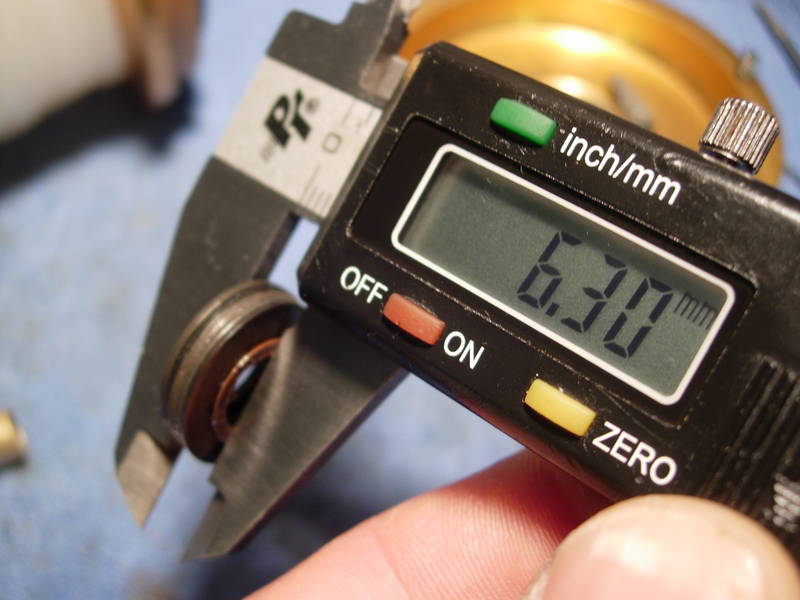
Now remember, we installed the bellevilles in the stock configuration of "()()". When I ran this reel through its paces, I found that I lost free spool when the preset knob was cranked down to 20 pounds of drag at strike. I got the same 30 seconds of free spool, but the maximum drag setting was too low for this particular customer. Here is the height of the stock belleville configuration of "()()" plus the thrust washer.
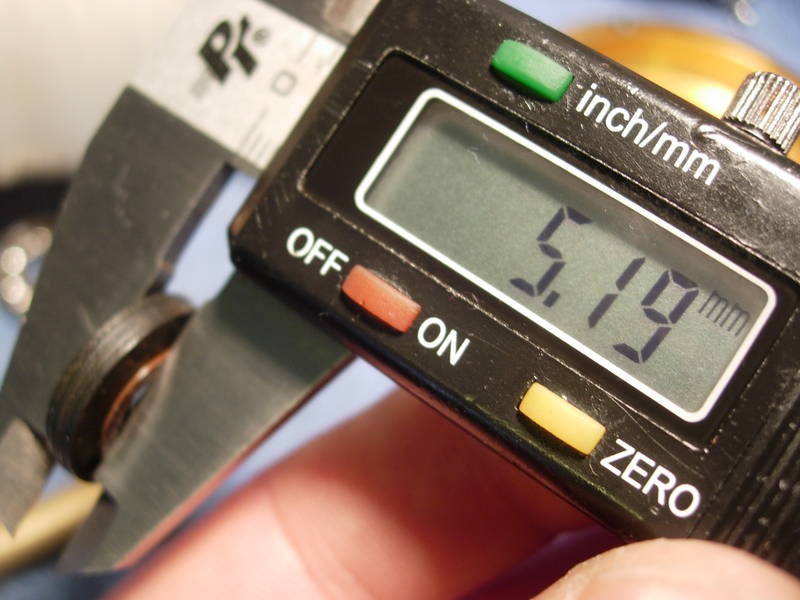
When the same four bellevilles were nested in a "(())" position plus the thrust washer, the stack was a little too short.
Adding a fifth belleville to the stack to make a "((())" configuration plus the thrust washer made the stack a little higher than it was originally, but I tried it anyway and it worked just fine. This configuration gave me 35 pounds at strike before losing free spool. And even at that extreme setting, I still got 30 seconds of free spool.
Gentlemen, we have a winner!
Copyright © Alan Tani Reprinted with permission of the author.
Order parts online for this reel(s):
https://www.mysticparts.com/PennParts/International.aspx#InternationalII2Speed
0 Comments