
 |
By Maureen Albertson |

Penn Defiance Levelwind Repair Walk-Through
Go here https://www.mysticparts.com/PennParts/Conventional.aspx#Defiance to order parts and access the schematics for the reels. This photo guide of the can be used as a reference for working on the Defiance reels, as well.
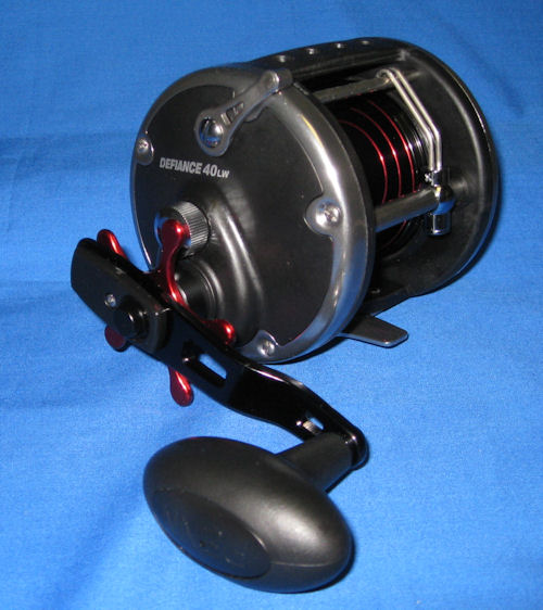
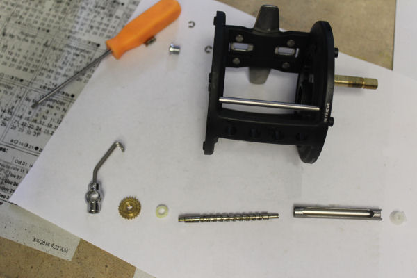
Today's victim for our reel-topsy table is the DFN40LW. As usual, take your time and lay out everything on a non-rolling surface in the order that you took the part off of the reel, in order to make reassembly easier.
- Quick jump to specific parts:
- Clicker
- Drag Washers
- Clutch (Anti-Reverse)
- Dogs and Springs (Anti-Reverse)
- Eccentric, Lever and Spring
- Gear, Pinion
- Levelwind System
- Star Drag - Tension Washer Stack
Or just start reading from here:
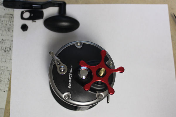
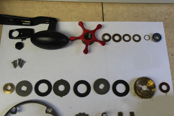
Start by removing the handle, star and washers
With the #10 drag star off, you can see the stack of tension washers underneath.
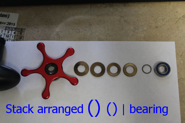
Star drag tension washer system with bearing.
There are 4 tension washers in two sizes cupped against each other under the star, then the little #56 shim at the bottom of the stack on top of the #55 bearing. The smaller # 18 tension washers curved cupped side towards each other in middle, with the larger #18A tension washers same way on top.
Remove all of the #38 screws on the handle side. #1 handle side plate off, showing the inside of the plate. #21 eccentric lever is in the open free spool position, which allowed removal of the #2 side ring and #1 plate from the reel. Working on the eccentric and spring happens in photo 9.
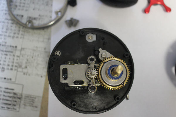
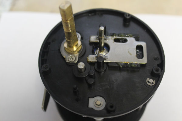
View of the handle side of the housing after removing the side plate. You can see the #55 bearing where it actually sits on top of the #9 brass collar on the #98 main gear stud, along with the drag stack underneath it.
Note the postion of the #11 eccentric jack, which is where it lies when the #21 lever is moved into the open position. You'll want these to be aligned in the same postitions when you put the reel back together.
I turned the reel around here and removed the entire main gear stack. Now you can see the #10 ratchet and the #4 dog positioning. When you are installing the dog on the ratchet, make sure the fingers are snug to the ratchet. If they get bent wider, the dog doesn't grip the ratchet and stop the spool from sgoing backwards.
Note the curved side of the ratchet is on top. The under side is distinctly flat. Do not install the ratchet upside-down or the dog will not catch properly.
Here you can see the order of the drag stack, plus the #4 washer (to the right) that goes between the gear and the ratchet and the #9 collar (all the way to the left) that goes on top of the stack.
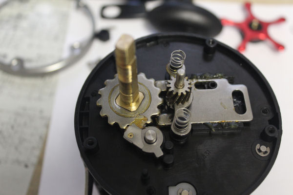
Back to breaking the reel down. Remove the #10 ratchet and #4 dog, #13 pinion, #12 yoke and the two #18 tension springs. Clean and replace as needed. If you need to get at the #55C bearing under the #98 stud, proceed to photo 12.
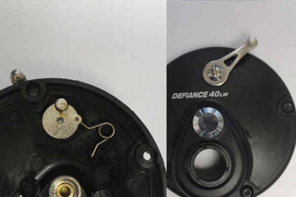
Photo 9, working on the handle side plate. The #21 eccentric lever moved to closed position, allowing the spring to relax. Let's remove the #19 eccentric as if we were replacing the #20 spring.
NOTE: brace the eccentric with your fingers while unscrewing the #22 lever screw.
4 photos installing the eccentric spring.
First, you can see the nub on the side of the eccentric that slides back and forth on the open side of the eccentric hole in the plate.
Then you tuck the eccentric into place, inserting one end of the spring up into the small hole in the lip of the eccentric and the other into the peg in the housing.
Holding the eccentric into the plate firmly on both sides, place the #21 lever onto the square end and start the #22 screw with your fingers, then tighten all the way down with screwdriver while still maintaining firm hold until the screw hits bottom.
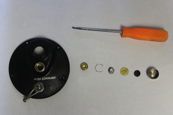
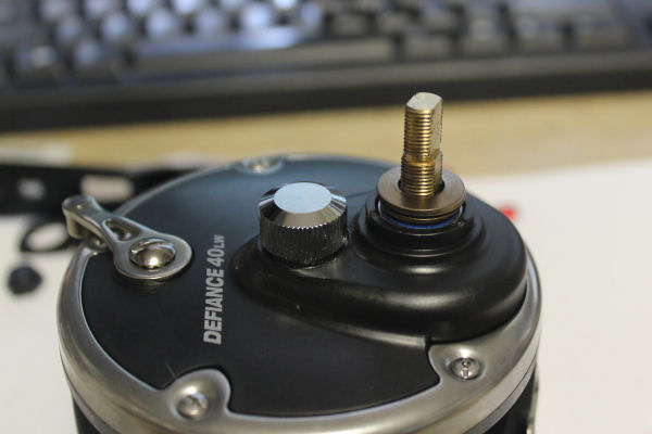
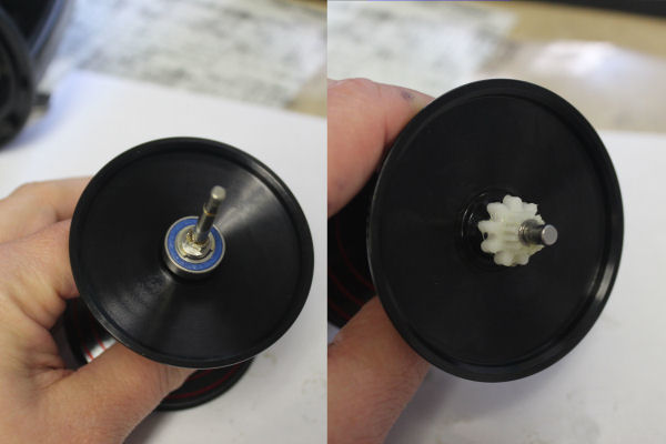
#26B spool tension cap laid out with the pieces underneath it separated.
Left to right: #55B brass bearing, #51 retaining ring, #41 spring, #40C metal thrust disc, #40D rubber thrust disc, #26B spool tension cap.
The #51 ring holds the #55b into the side plate and is unlikely to fall out, so if you lose the knob overboard, you'll have lost #41, #40C, #40D and #26B.
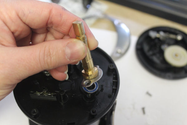
Unscrew the two #38C screws and lift off the #98 stud and #98A stud plate, and you can pull and check the #55C bearing.
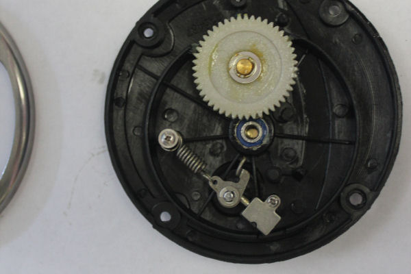
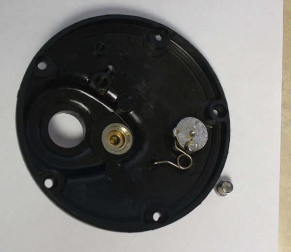
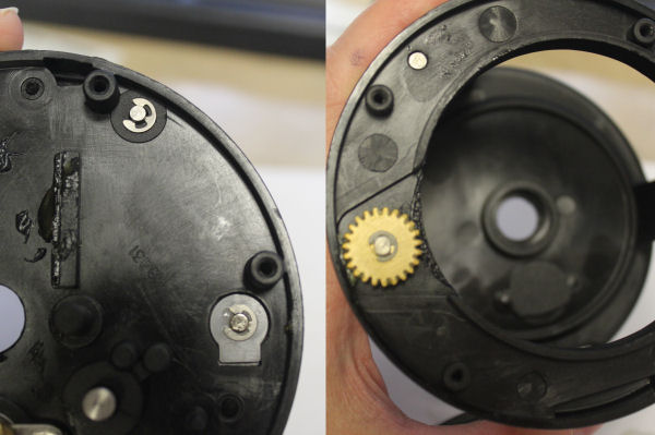
Unscrew the #39 screws on the non-handle side to assess the clicker and levelwind componants. You can pop out the #51 retaining ring if you want to check the #55A bearing in center. You should be able to do so without removing the #64 idler gear. If you need to replace the idler gear, just push off the #69C retaining clip to remove. NOTE: The idler gear has two small #64A washers on each side of it. Be careful not to lose them if changing out the gear.
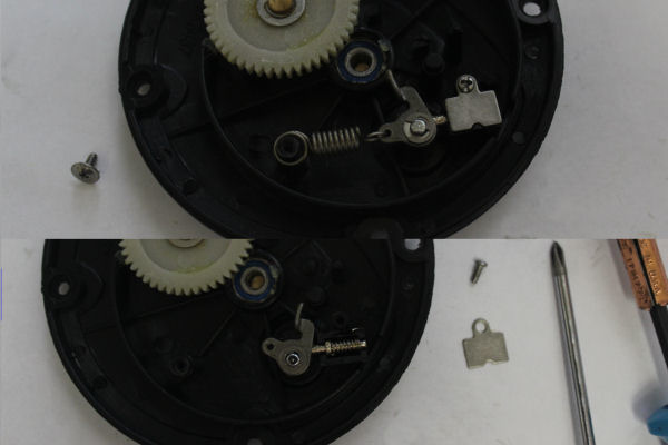
Upper image: Unscrew the #38A screw to change out the #62 click spring.
Lower image: Unscrew the #38B screw to remove #62 tension plate if you need to change out the #62A coil spring.
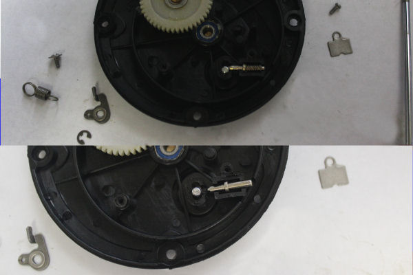
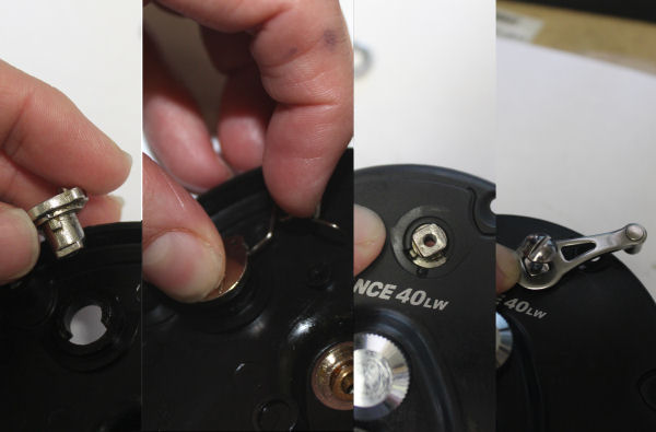
Upper image: Push off the #69 c-clip to remove the #60 flat washer and #35 click tongue. Use a finger to try and keep it from flying across the room while gently pushing it with the flat screwdriver. You can now access the #62B click tension shaft and #62A coil spring by gently lifting them with screw driver or bearing puller tip.
Lower image: When reinstalling the #62b shaft, short end goes in first towards the click button post in the plate as shown here.
The spool. Remove #69A c-clip if necessary to inspect or change the spool bearing.
Inspect the teeth on the #66 click ratchet, also held on with a #69B c-clip.
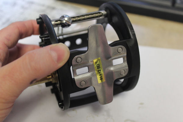
Housing and Levelwind system. The stand is part of the housing, so if it is damaged, the housing itself needs to be replaced.
Levelwind components are held on the housing by c-clips (3 of #69).
Unscrew the #48 pawl cover screw and inspect the teeth on the #47 pawl.
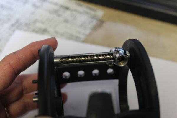
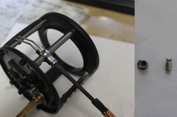
Turn the worm and inspect the groves. Any sign of a nick or cut that shouldn't be there means that the worm should be replaced. Pop the two #69 clips on either side of the worm if you need to work on the worm and or line guide. (Two flatheads helped for the clip on the #43 plastic bushing.
Long skinny end of the worm goes into the #43 bushing side. Short thicker end holds the gear and bushing.
For the walk through, I did not remove the #58 post. Do so if it needs replacing.
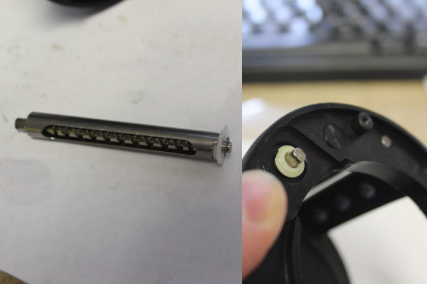
It's easiest to re-install this part of the worm assembly first. Slide it back into the housing, through the #46 line guide, and set it into place with the flat end of the bushing set into the housing. Then install the #42A worm gear and #44 bushing with the other #96 clip.
Line guide NOTE: You won't be able to get the #69 clip onto the #42 gear if you do not turn the shield/worm so that they are sitting at the correct angle, because the end of the worm won't stick out far enough if it is out of position. Turn it, install the #47 pawl in the #48 pawl cover screw to secure the guide to the worm, then put the #69 clip on.
Order parts online for this reel(s):
https://www.mysticparts.com/PennParts/Conventional.aspx#Defiance
0 Comments