 |
By Maureen Albertson |
A sample breakdown of the CQR5000 Conquer to help with re-assembly of these reels.
- Quick jump to specific parts:
- Bail Spring
- Cam and Trip Levers
- Clicker
- Clutch (Anti-Reverse)
- Crosswind
- Drag Washers
- Gears, Main Gear and Crosswind Gear
- Gear, Pinion
- Handle
Or just start reading from here:
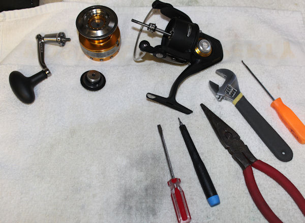
I'm only using the key #s from the drawing. For full part numbers, see page 2 of our schematic: CQR5000 Schematic
Bail Assembly
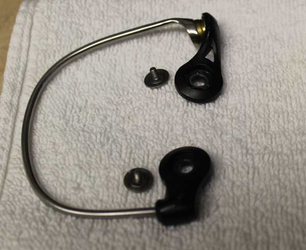
Unhook the bail arm to work on the bail spring. You can remove just that side if wished. I removed it completely for the purposes of the breakdown, then put it back on. This series has a nice, strong bail wire, one of the features we really like, as it's less inclined to bend out of shape.
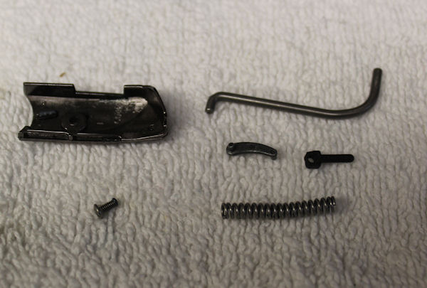
Bail spring parts and cover, on the same side as the line roller assembly.
#22 screw, #27A cover. The #28 trip lever, #34C pivot arm, #34B pivot lever and #32 bail spring.
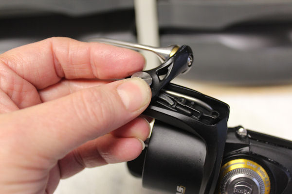
When installing the #34B and #34C, they need to be fully extended. The bail should be in the open position as shown. You can see the positioning of the #28 trip lever along the side, the short end goes up into the #34 bail arm. Patience is required when installing the smaller parts! Once these parts are in position under the #34 bail arm, tighten down the #31 bail arm screw to lock it all in place.
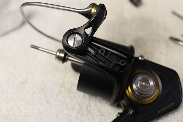
Installing the bail spring. Here, the small metal #34B pivot lever is in place with one end in the #34 bail arm and one in the square slot on the #34C pivot arm.
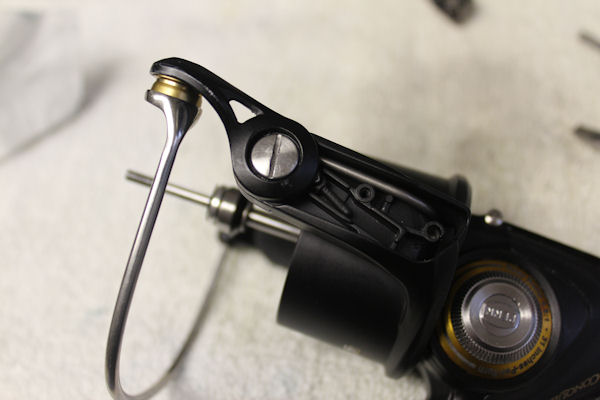
Turn the bail like so to the closed position, with the lever and arm folded, for installing the spring.
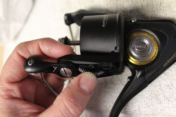
Slide one end of the spring onto the arm and curve it to tuck the other end into the rotor.
This is where problems may occur. The early bail springs were lighter/looser coils than the one shown here. The later springs are heavier/tighter coils as shown. This spring produces a lot of tension, and may blow itself right out of position. ONLY IF you are having this problem, cut about a bit off the end of the spring (about 2 coils, maybe 3 tops) to reduce the tension a bit. BE CAREFUL NOT TO CUT TOO MUCH OFF, or the spring will loose too much tension and the bail won't flip properly. Again, DO NOT do so unless you bail spring is repeatedly displacing.
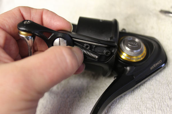
Once both ends of the spring are in, gently flatten the curve into place and slide on the cover.
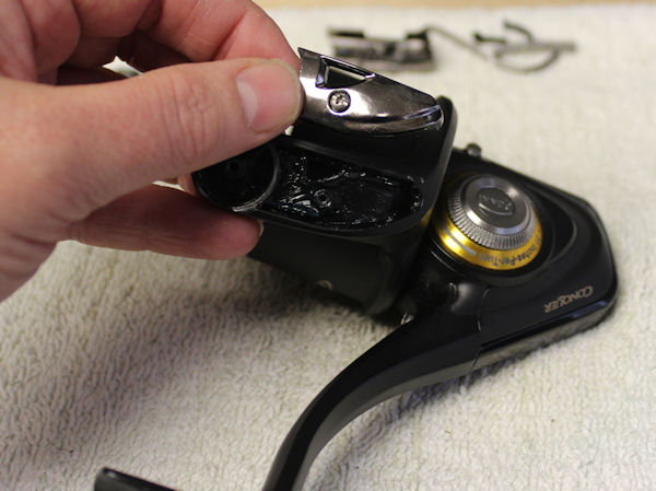
Cover on the opposite side of the rotor is purely for decoration, there is nothing under it.
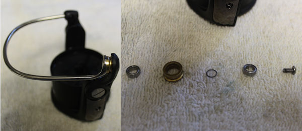
Line roller pieces.
#132A line roller washer goes inside the line roller, in between the two #35A ball bearings.
Underneath the spool
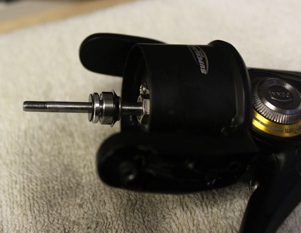
The shaft as shown after removing the spool.
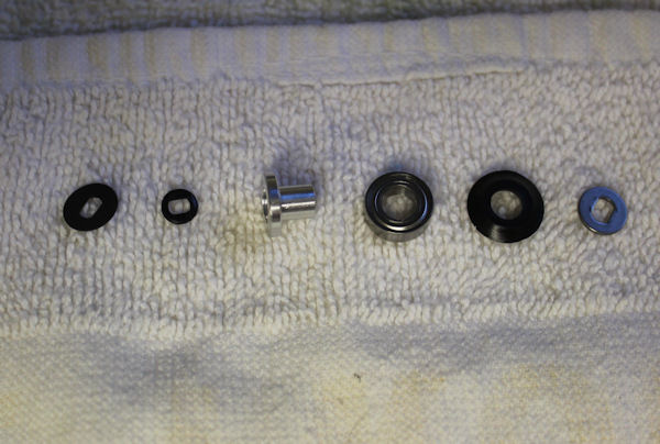
Separated shaft parts from under the spool. From left to right:
#60 Spacer washer, #60A O-ring, #60C bearing sleever, #60B ball bearing, #60S seal, #60W spool shaft washer.
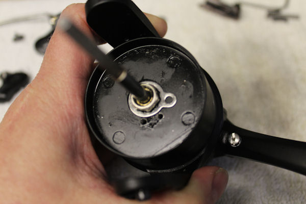
Rotor nut, washer and screw. In position.
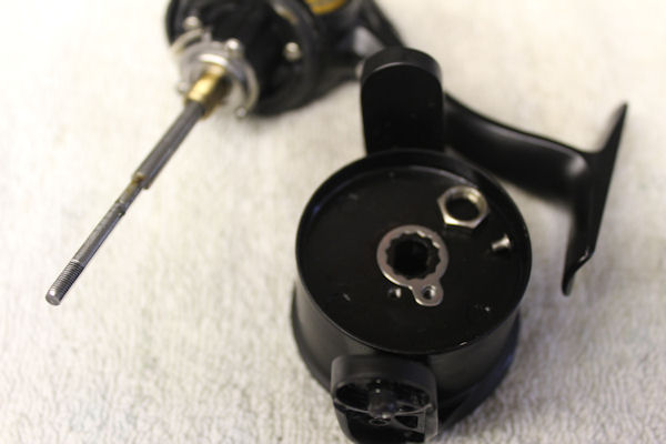
Rotor nut, washer and screw removed.
REASSEMBLY NOTES: Line up the flat edge of the pinion to the flat edge in the rotor. Push pinion forward using a flat head screwdriver from open hosuing so that rotor and pinion can be secured with the nut. (In this model, the rotor nut keeps the pinion in the proper position, there is no pinion stop in the housing)
The Clutch (Anti-Reverse)
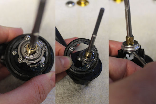
Clutch Assembly. Note how the spring is attached for future reference.
Unscrew the two #28S screws and gently remove #28E friction ring cover and #28D friction ring as a unit. I left the screws in it.
Unscrew the three #21A and remove the #21 bearing retainer underneath. (shown below after removal)
A turn of a screwdriver to assist in pushing out #21B collar and its #20A bearing to get at the clutch. Notice that the metal sleeve from the center of the clutch is missing - it is still on the shaft with the pinion. See notes in the pinion section.
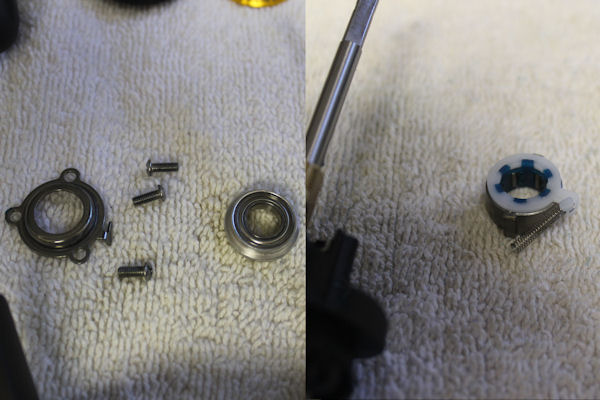
Retainer with collar and bearing. #98C clutch assembly removed from the shaft. The clutch itself is only sold as an assembly so if any part of it is bad, you need to replace the whole thing.
Accessing The Gears
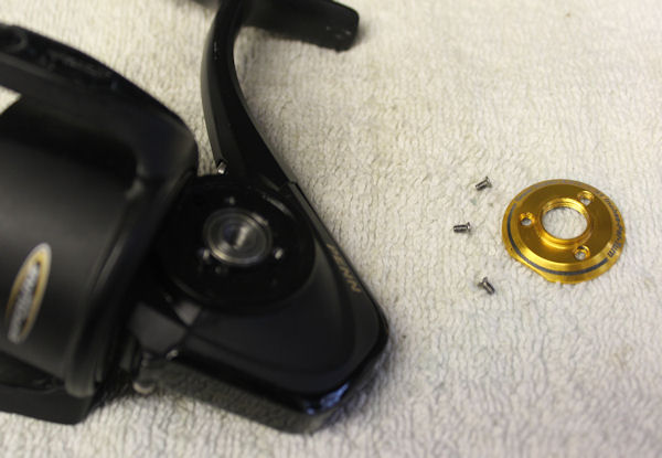
Handle side cover and screws
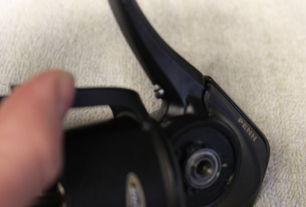
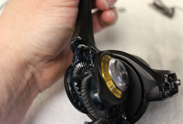
Above are two photos of #46 screw and #46S spring for rear access cover. Shots taken front view and back. Use this if all you need to do is clean and lube the gears.
In the rare even off the 46 or 46S needing replacing, you basically have to rip the pair out to do so.
NOTE: It is recommended that you do not over-grease gears; it is not necessary to pack a reel with grease as this can cause it's own problems.
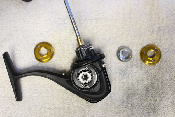
#233 bearing cover and two #232 bearing retainers removed.
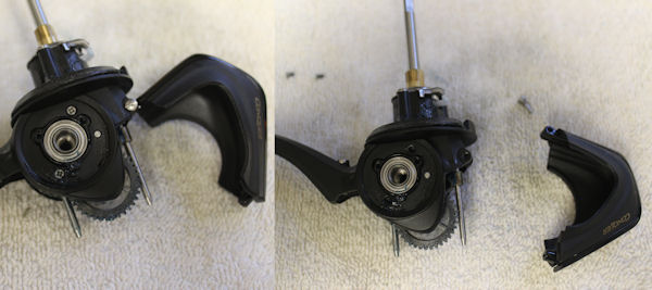
OPTIONAL: Remove the #46 screw if you need to take the #45 maintenance hatch off all the way to replace it.
Accessing The Pinion Gear
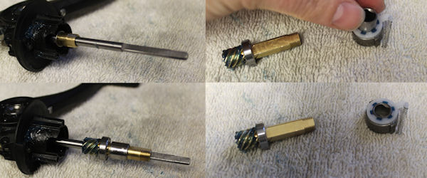
Once the clutch is out of the way, you can slide the pinion gear and bearing off of the shaft. The spacing sleeve may have come out of the clutch, if so, just slip it back inside.
BEARINGS: During your reel repair, check all the bearings to make sure they spin smoothly. If the pinion gear bearing seems a little rough, move one of the main gear bearings to the pinion and put the pinion bearing on the main gear (they are all the same bearing). Rotation will extend the use of the bearings as the pinion bearing seems to go bad first. If a bearing is extremely rough/gritty or won't spin at all, replace it entirely.
Crosswind and Main Gear
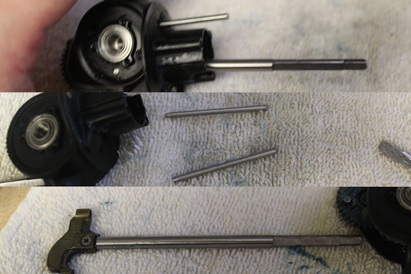
The two #43A crosswind block pins can be pulled out from the clutch side, then you can slide the #39 spool shaft out from the main gear side with #43 crosswind block still attached. Check for wear.
Give a gentle tap to remove the pins if needed.
NOTE: You'll see a shallow groove/indentation on the longer flat part of the shaft. This is not damage, it is part of the design.
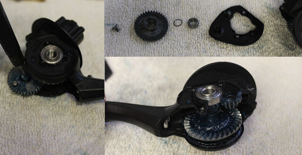
Crosswind gear parts.
#231B crosswind screw, #35A bearing(not shown, it's tucked in the other side of the crosswind gear), #231 crosswind gear, #132A washer, #35A bearing.
#132A washer goes in between the bearings inside the gear.
Removed the #1A housing plate, to expose the #20A ball bearing and the #64 idler gear above the main gear.
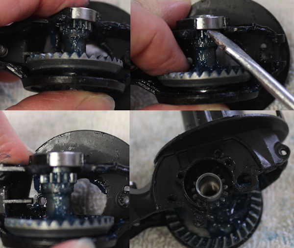
Note the gap under the main gear. To remove the bearing from the main gear, gently push the bearing up with the screwdriver, while at the same time, pushing the main gear down to close the gap. This will make a gap under the bearing, in which you can then turn the screwdriver tip to work the bearing off.
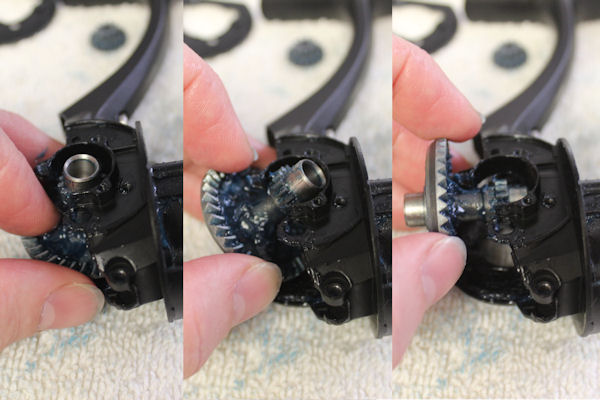
Removing the main gear, left to right. To reinstall, same steps in reverse.
Also remove the bearing from the bottom of the main gear.
As noted before in pinion section, rotate bearings now if needed. Replace bad bearings.
NOTES:If the bearings do not move smoothly on and off the main gear, smooth the main gear shaft with emory cloth.
A little lube on the inner ring of the bearings when you put them back on will make removal later easier.
Clean off all old grease from all gears, inspect teeth on all the gears thoroughly, then regrease and reinstall.
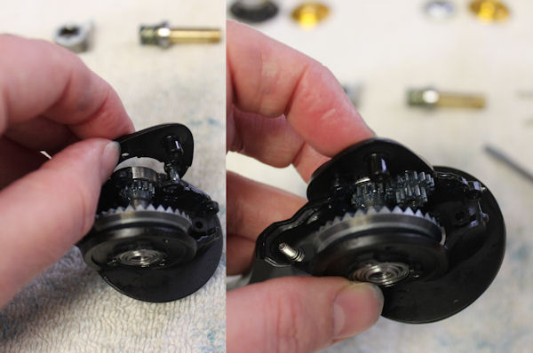
Reassembling the body of the reel. The main gear and bearings are reinstalled. #1A frame and #64 idler are next as shown.
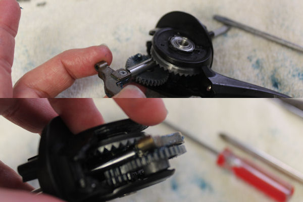
Slide the crosswind block and shaft assembly back into the gap between the main and crosswind gears.
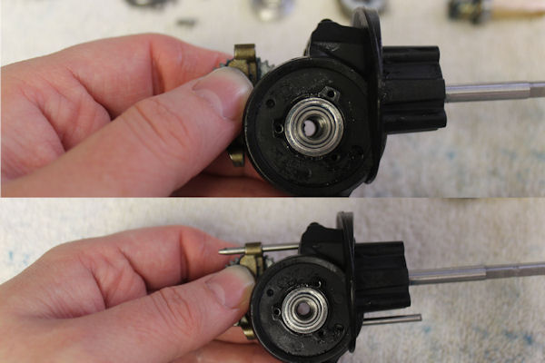
Line up the groove in the #43 crosswind block to the #231 crosswind gear stub. Holding the crosswind together with your fingers, insert the #43A crosswind block pins until flush with the housing.
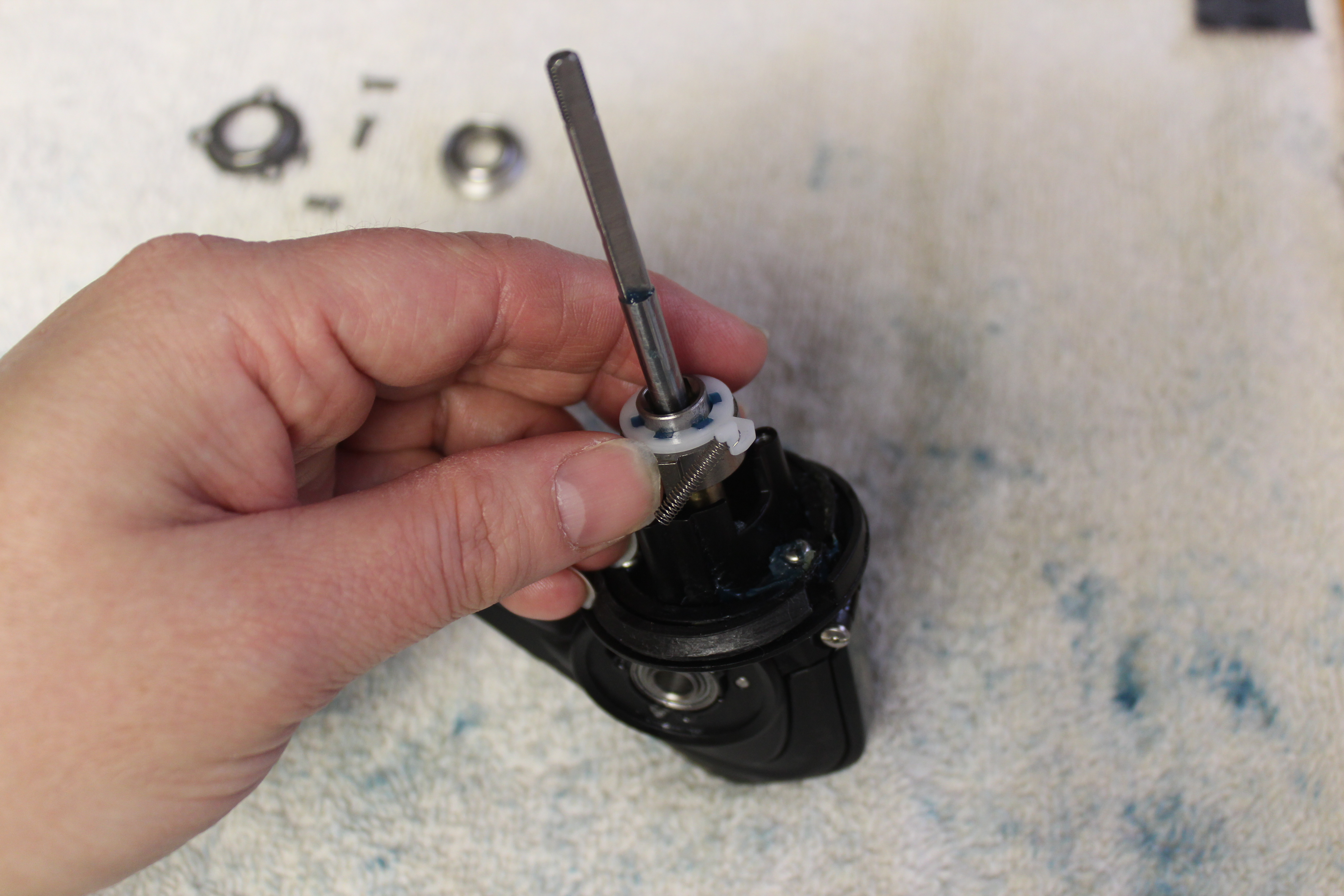
When reinstalling the clutch on the shaft, line up the flat edge of the inner sleeve with flat pinion edge. Line up the square edge of the clutch with the same shaped cut on the housing.
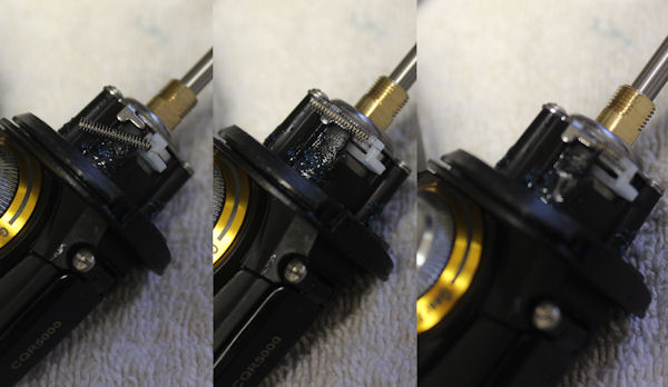
Quick set of shots installing the #97 clutch spring.
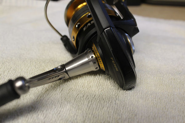
Handle Assembly. Yes, that gap at the collar is supposed to be there.
The Spool and Drag System
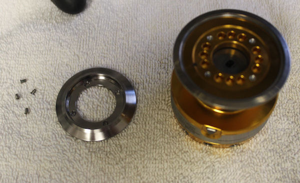
Here I removed the top of the spool. I'm not really sure why this comes apart. It doesn't allow access to the drag washers and appears to be purely cosmetic. You get at the drags from the underside of the spool.
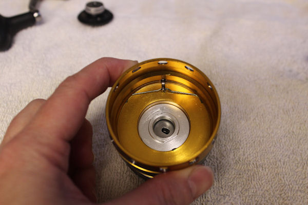
The underside of the spool #47e spring holds the 47D line clip on. This is NOT the clicker like on most older Penn spinning reel spools. We'll get to the clicker in the spool breakdown.
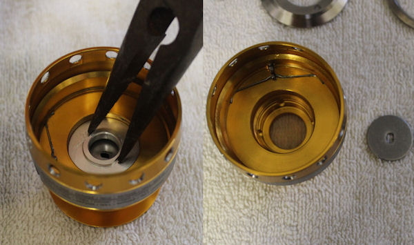
Underneath the spool, you unscrew the back of #48B counterclockwise to remove the cover and access the drags. Inside of emptied spool also shown.
NOTE: A small amount of grease here on the threads of 48B where it screws on would be helpful for future removal, since salt/corrosion in here might make it hard to unscrew.
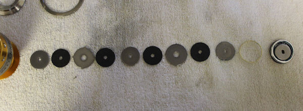
Drags laid out in order.
#57, #56, #58, #56, #57, #56, #58A, #56, #57
then #48D white teflon spacer washer and the clicker assembly of [#48A, #48, #48B, #48E]
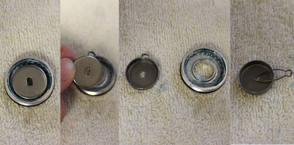
Breaking down the clicker assembly of [#48A, #48, #48B, #48E]
Lift out the pair #48A spool click retainer and #48 spool click from the inside of 48B.
Pinch #48A spool click retainer to remove it if needed.
The #48E O-ring is just visible here on the back of the #48B click housing.
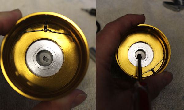
The drag washers must be lined up. If mis-aligned, the spool will not seat all the way down. Use a flat head screw driver to straighten and watch the flat edges of the drag washers to make sure they line up as you are snugging down 48B. Do not overtighten.
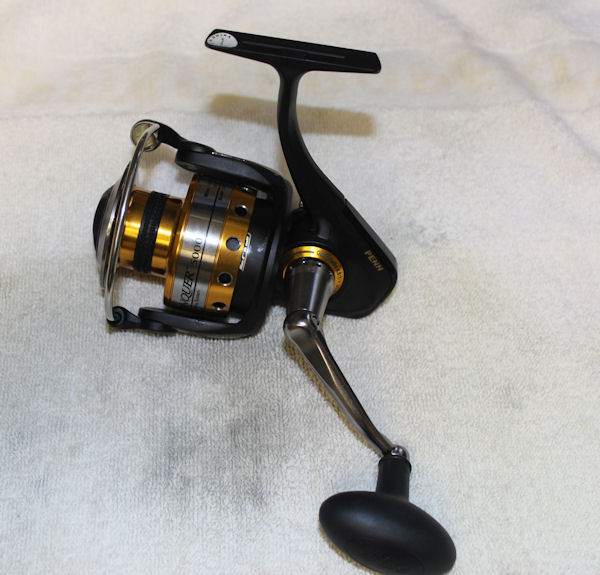
The Conquer 5000 Re-Assembled.
Order parts online for this reel(s):
https://www.mysticparts.com/PennParts/Spinning.aspx#Conquer

1 Comments