| By Maureen Albertson www.mysticparts.com ©Mystic Reel Parts LLC Questions? |
We've gotten many emails about how to assemble certain parts of the SSV Live Liner reels, so we are doing a breakdown of the SSV6500LL as a sample to help with re-assembly of these reels. TOOLS: Standard and phillips head screwdrivers, adjustable or socket wrench, micro phillips screwdriver size PH0, tweezers.
- ** Design Change #1: Housing & Crosswind Gear
- Bail Spring and Trip
- Clicker, Spool
- Clutch (Anti-Reverse) and Pinion Gear
- Drag Washers
- ** Design Change #2: Gears, Main and Crosswind
- Line Roller Assembly
- Live Liner Drag Switch, Cam and Spring
- Rear Drag Assembly
- Rear Clicker
- Rotor and Spool Shaft
- Trip Lever Assembly in Cover
- Quick jump to specific parts:
Or just start reading from here:
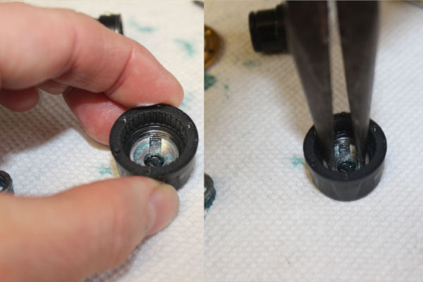
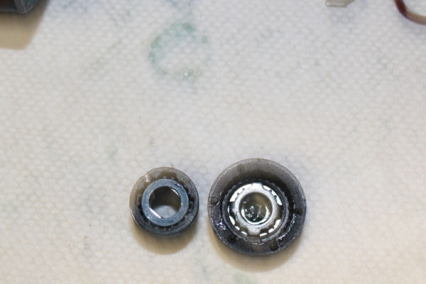
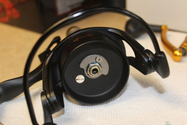
DESIGN CHANGE #1: HOUSING & CROSSWIND GEAR
They changed the inside diameter of the crosswind gear and the size of the corresponding pin on the housings of several of the SSV reels. More notes about the design change here: https://scottsbt.zendesk.com/hc/en-us/articles/204309045-SS-Reels-SSV-Gear-Design-change
NOTE: The #231A screw in the center of the #231 crosswind gear will strip easily! Needs a micro phillips head size PH0 to remove it.
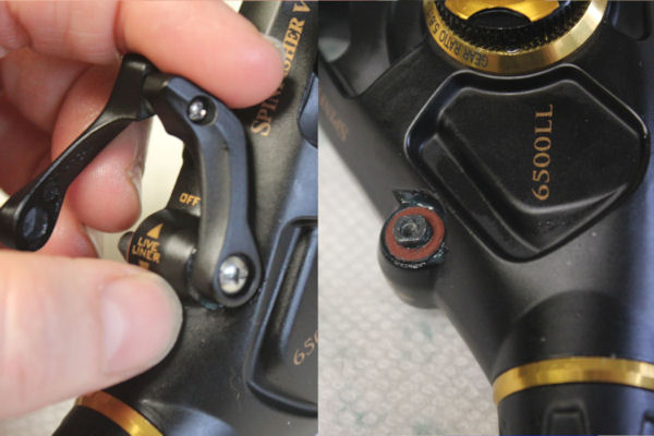
Start by removing the drag knob and spool and setting those aside. On this reel, you have to get the liveliner lever arm out of the way before you can remove the #45 cover. On the drag lever switch, loosen the TOP screw #70B so that you can lift #70 left drag switch lever off of the tip of the #72 switch lever cam sitting in the housing and out of the way (you don't have to remove the lever piece entirely unless you want to replace it.
NOTE: We are doing this stage of dis-assembly with the lever in the UP position as shown in photo. When reassembling, work backwards to the positions that parts were in during breakdown. The lever must be in this position to interact with the other levers in the #45 cover as shown in the guide farther along.
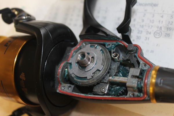
Now you can remove the #46 cover screws and lift off the #45 housing cover.
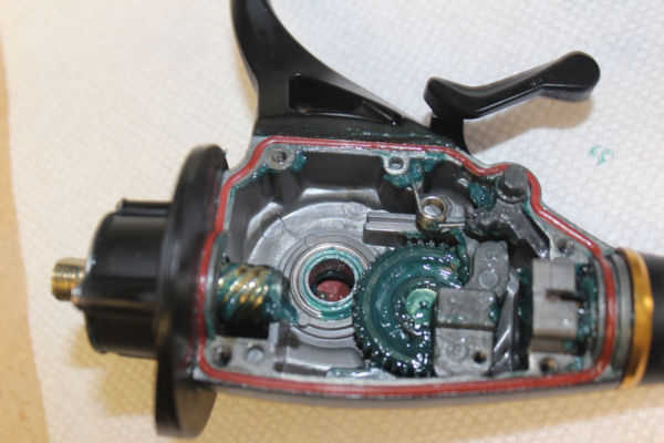
Photo above shows the #70 lever swung away, and the main gear assembly with #74E triple pawl lever on top and the positioning of the drag lever switch cam #72 that the lever sits on, with it's #71 lever spring.
Here, the #74E pawl cover has been removed so that you can see the #74F triple pawl spring.
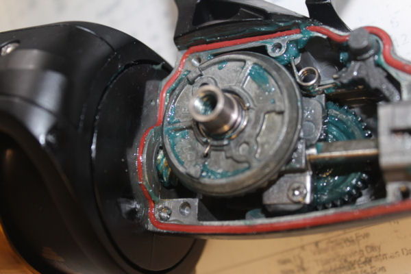
**THERE IS A DESIGN CHANGE INVOLVED! Photo above shows the original main gear and spring setup.
***DESIGN CHANGE #2 NOTES:
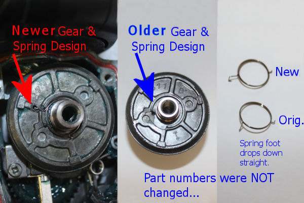
They moved the hole in the main gear closer to it's shaft, and made the long foot of the spring drop straight down into the hole. Penn did not change the part numbers after they changed the parts. If you need to order a new #8 main gear, make sure you order another #74F as well, so that they are compatible!
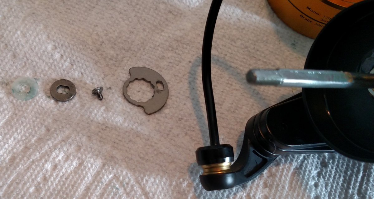
REAR DRAG ASSEMBLY
Taking apart the #88 rear drag to service it, if needed. Start by removing the #88D retainer. There is a notch to the right that you can set a screw driver against. Push the retainer up and to the left a little, then put the tip of the screwdrive into the gap you created and lever out the retainer.
You can now slide out the rear drag assembly.
Take the rear drag assembly apart carefully, laying it out in the order shown on the schematic.
NOTE: I found a 2nd #85 drag washer inside the #82 rear drag hosuing that was not on the Rev. 2 Penn schematic.
Top row: 83A washer, #83 ratchet, #88D retainer, #88E seal, #88B gold ring, #88C screws, #82 housing.
Bottom row: #85 washer, #84A retainer w/#84 clicker installed in it, #85A metal keyed washer, #85 washer, #85B eared washer, #86 spring, #86A nut inside #88 knob.
#82 housing with #87 clicker and 87A clicker ring attached to it.
REAR CLICKER/h2>
Inside of #82 housing with #84A retainer w/#84 clicker installed in it.
If you need to change out the #88 knob or the #86A nut, use open pliers to put preassure on the inside of the nut so that you can turn it. The threads are reversed, so "RIGHTY LOOSEY".
Some reassembly notes. LEFT: Line up the notches in the #82 housing with the side prongs on the #85B earred washer when you put the #88 assembly back together.
RIGHT: The ears on the #85B washer set down into the notches in the #86A nut.
To reinstall the #88D retainer for the rear drag assembly, put the left arm in first. Use the tip of the screwdriver to push the right arm tip inwards, then put down from the top to snap the retainer into place.
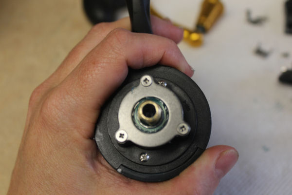
ROTOR AND SPOOL SHAFT
>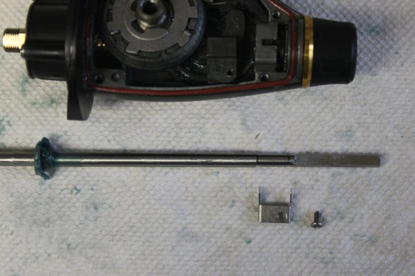
To access the clutch, pinion gear and bearings, first you have to remove the rotor. Unscrew and remove the #43A osc. slider glide (AKA crosswind block plate) inside the housing. This style has two hooks on it the fit against the shaft on either side of the #43 osc. sl(AKA crosswind block).
After sliding out the #39 spool shaft, remove the #38A screw, #95B locking plate and #38 rotor nut to take off the #27 rotor.
NOTE: As shown above, if you just need to work on the rotor or under it, without touching the gears in the housing, then you can skip taking the shaft out and just remove the spool, then take off the washers on the shaft to access the rotor nut assembly.
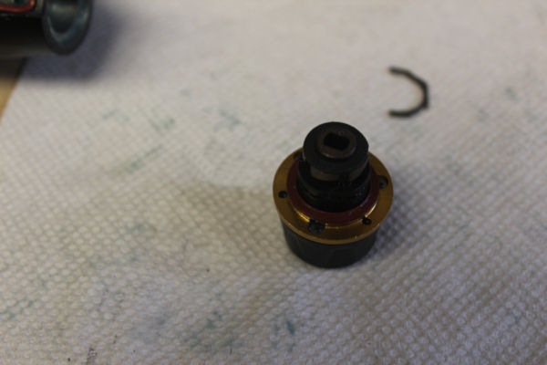
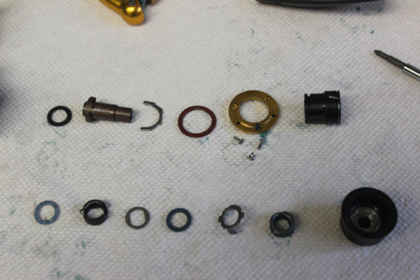
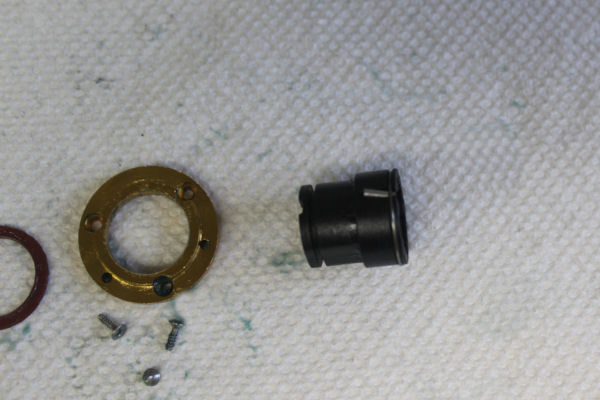
CLUTCH (ANTI-REVERSE) AND PINION GEAR
Underneath the rotor, you can access the anti-revers clutch, pinion gear and bearings. Remove the #21A screws and #21 bearing cover.
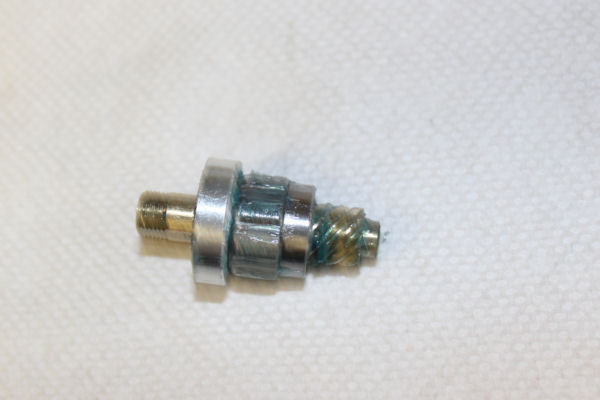
Slide out the assembly.
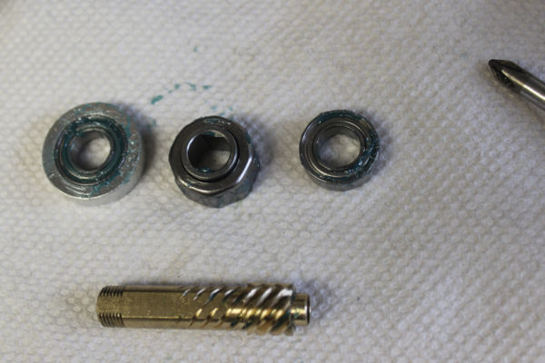
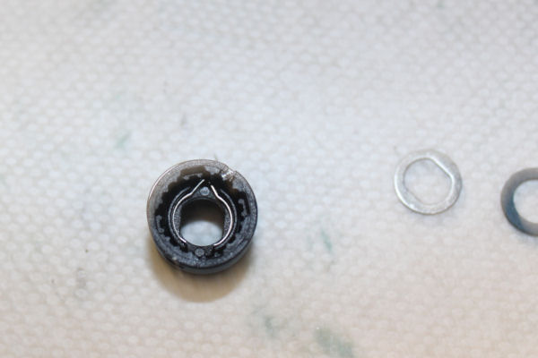
Inspect #20 bearings for smoothness. If only slightly rough, keep them for another season. If you cannot spin the bearings or they are extremely gritty, it's time to replace them.
Check the teeth on the gear and make sure there are no cuts in the #21B collar that would make the reel sound rough.
If the anti-reverse has been malfunctioning, make sure the interior of the #98 clutch is clean and all of the small pins are in place. If you reassemble the reel and the a/r is still failing, it's time to replace #98.
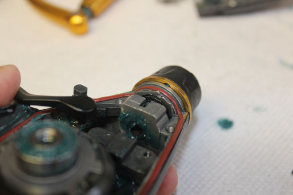
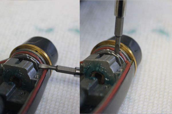
LIVE LINER DRAG SWITCH, CAM AND SPRING
This photo shows the #70 swung out of the way and the positioning of the #71 spring and the #72 switch cam, with the main gear out of the way to work on them.
NOTE: The #231A screw in the center of the #231 crosswind gear will strip easily! Needs a micro phillips head size PH0 to remove it.
If it needs changing, the #71 spring can be installed without removing the #72 cam.
If you need to replace the #70A arm or the #72 cam, remove the larger #70C screw.
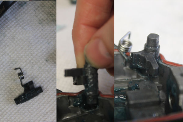
#72 cam removal and installation is simple.
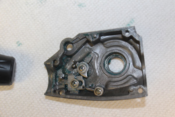
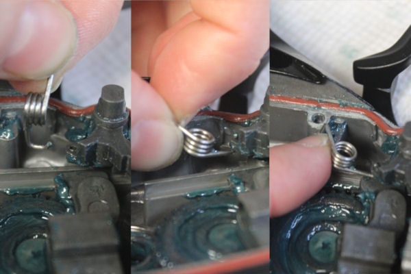
The inside of the #45 cover when removed. Note the positioning of the levers and springs. This is the position that they belong in when the live liner lever is in the UP position as shown at the beginning of this guide.
If springs need replacing, slowly remove the pieces and place them in order for easier reassembly. Note that you can't see the hooked end of the #74B spring, as it is underneath the #77 stop claw.
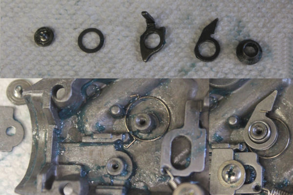
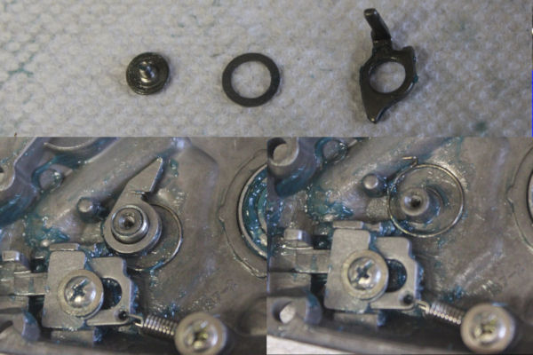
Here the levers have both been removed and the #77 stop claw move aside, so that you can see how the hooked end of the #74B spring sits in the housing cover. The upright hook on the #74B spring then hooks onto the #74 trip lever when you reinstall it, as shown to the right.
BAIL SPRING AND TRIP INSTALLATION
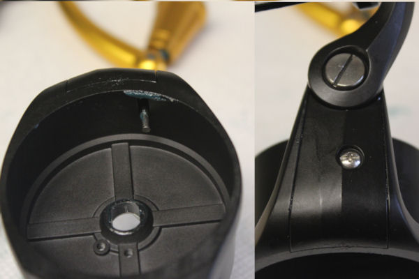
This work is done with the #24 bail in CLOSED position.
LEFT: Underside of the #27 rotor showing the tip of the #28 bail trip lever.
RIGHT: the #27A rotor cover. Remove the small #22 screw to access the #32bail spring.
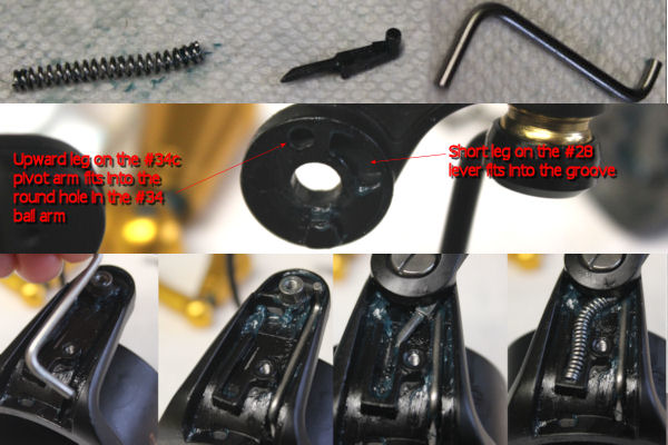
TOP: The #32 bail spring, #34C pivot arm and #28 bail trip lever.
MIDDLE: Connection of the #34 bail arm, notes in photo.
BOTTOM: Installation of the pieces. The #34C should be place so that the little upward arm fits in the hole in the #34 bail arm.
LINE ROLLER ASSEMBLY
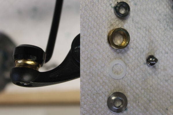
LEFT: Line roller assembled in the #34 bail arm and #24 bail wire.
RIGHT: Top to bottom as positioned in the left photo. #35A bearing goes into the #35 line roller, then the white #132A washer sits between the line roller and the #132 line roller washer. The number #36 screw goes into the bail arm and through the #35 line roller to screw into the seat on the #24 bail wire.
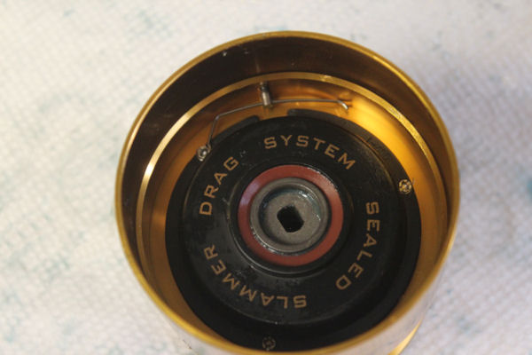
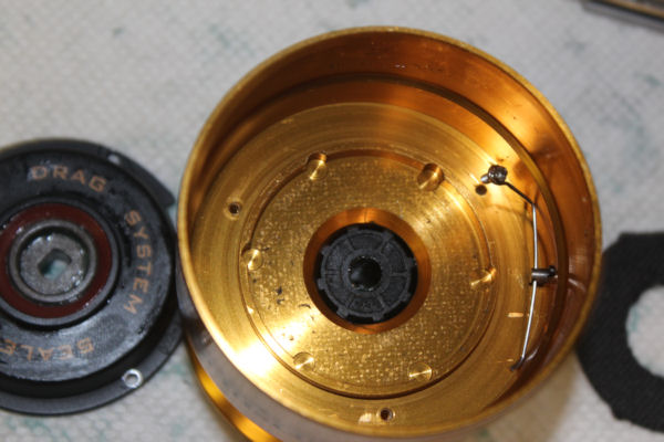
DRAG WASHERS AND SPOOL ASSEMBLY
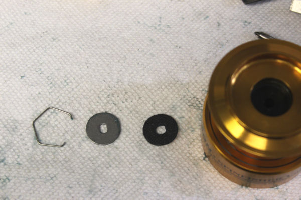
Upper part of the spool, the order of the washers. For the purpose of this walk-thru, I did NOT remove the #63 spool bushing, which remains inside the top of the spool. The #56T HT100 fiber washer goes into the spool first, the the #57T keyed metal washer, then the #51 retaining spring sets into the groove in the top of the spool to lock them in place.
The underside of the spool. Note the positioning of the #47F line clip retainer, which is held in place on the lip of the #47C drag cover by one of the small #22A screws (micro phillips head screw driver size PH0 required). The #47D line retainer post goes through the #47E bushing, through the hole in the side of the spool. The #47F line clip retainer goes through the small hole in the side of the 47D post as shown above.
Unscrew the 3 #22A screws (micro phillips head screw driver size PH0 required), to access the lower spool drags. Note that the #48S red drag cover seal will probably jump out of place. Set it aside for the moment. You can see the notches where the drags sit in the spool.
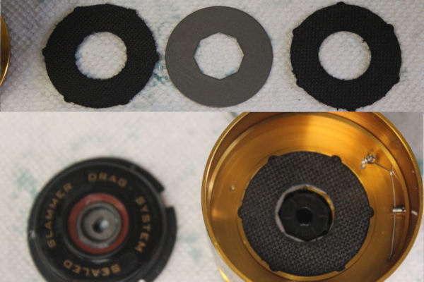
The order is simple. A #56 HT100 drag washer goes in first, then the #57 metal washer then the second #56 washer. In these photos, the second #57 metal washer is still connected to the #117 drive plate and is not shown.
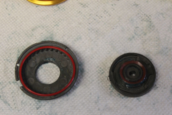
The #48S drag cover seal sets into the #47C drag cover as shown to the right here. The #117 is upside-down in this photo so that you can see the #47S drive plate seal installed on it, and the #48 spool clicker inside it. You would then flip it over into the #47 cover to reassemble.
Clicker
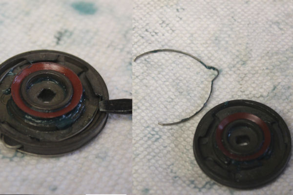
Removing and re-installing the #48 spool clicker is fairly simple. Just use the tip of the screw driver to pop one arm loose, then grab the looped end and slide it out of the #117 plate. Put it back in the same way.
DRAG ASSEMLBY TIP: I found it easier to stack all of the bottom spool drags into the 47C cover, hold the spool in one hand and bring the stack up from underneath to set it in place in the spool, then turn it all over to screw the cover down again.
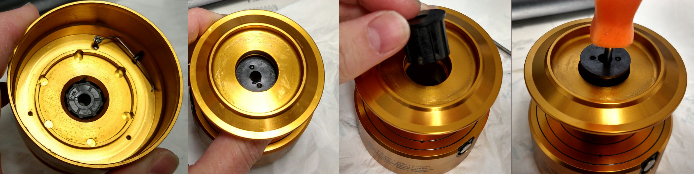
Removing the spool bushing is done after taking off top and bottom drag washer systems. Push the bushing up from the underside of the spool using level pressure with a screw driver handle. Reinstall it from the top as shown. Center the bushing and push straight in using screw driver handle with level pressure until it stops.
Order parts online for this reel(s):
https://www.mysticparts.com/PennParts/Spinning.aspx#SS5thGen


3 Comments