| By Maureen Albertson www.mysticparts.com ©Mystic Reel Parts LLC Questions? |
 By MizMo
http://www.mysticparts.com/
Penn 220GR Repair Walk-Through
Go here https://www.mysticparts.com/PennParts/Spinning.aspx#Graphite to order parts and access the schematics for the reels. This photo guide of the can be used as a reference for working on the larger 230GR, 240GR 250GR reels as well.
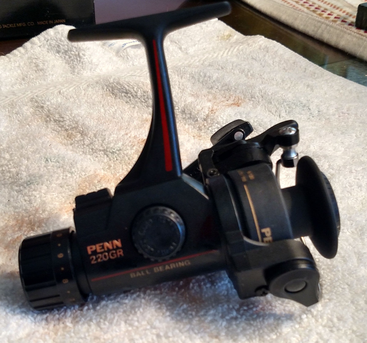
Assembly guide for the 220GR types series. As always, reference the schematic for the specific model that you are working on. Example here is the 220GR Schematic. I am using the key # from the drawing, which you match to the part numbers on page 2 of our online .pdf schematics.
CLICK ON ANY PHOTO TO VIEW LARGER SIZE
RECOMMENDED TOOLS:
- 1/4" and 1/8" Flat Head
- small adjustable wrench
- Medium Philips Head
- small bent tip bearing puller (for lifting/separating)
Quick jump to specific parts:
- Bail Wire, Line Roller, Bail Spring
- Cam and Trip Lever Positions
- Cast Lever AKA Trigger
- Housing & Main Gear
- Drag Washers
- Gear, Pinion
- Reassembly of Shaft and Main Gear
Or just start reading from here:
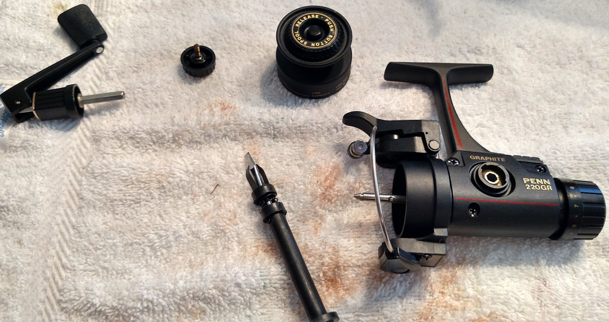
Start as with most spinning reels, by accessing the main gearing in the housing, so that we can remove the spool shaft to get under the rotor at the pinion assembly. Remove the spool and handle and set them aside. Remove the three #46 housing cover screws and remove the #45 cover.
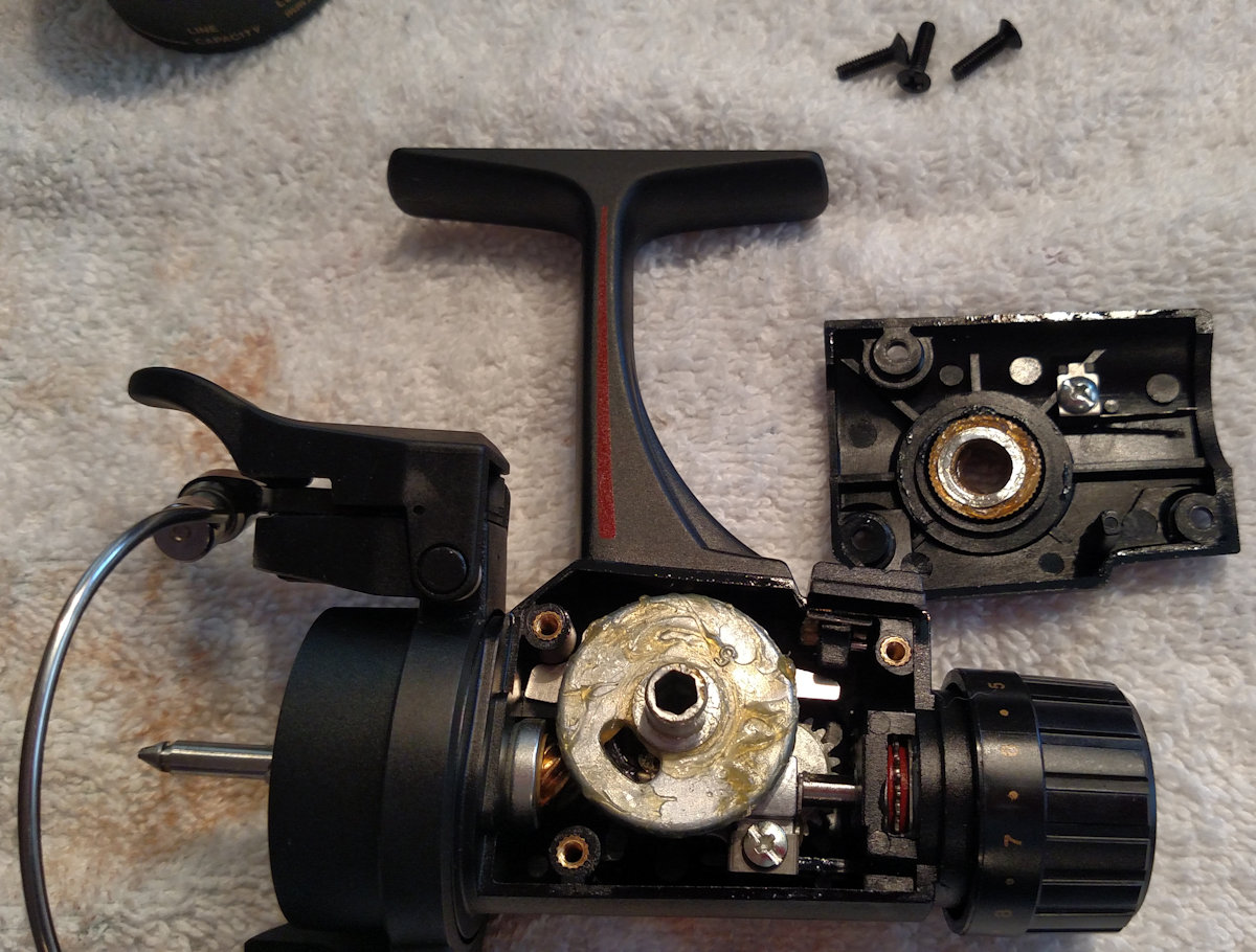
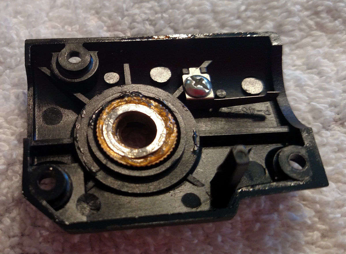
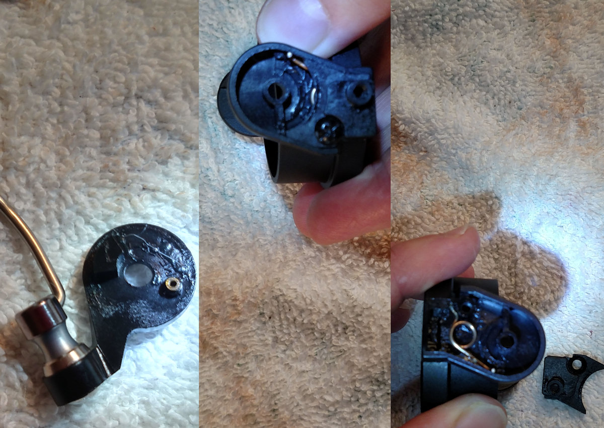
Closeup of the #45 cover so that you can see how the #49 click spring seats on it. You can also see the #8A shim sitting against the #2A bearing. Don't lose track of that shim. I left it with the cover.
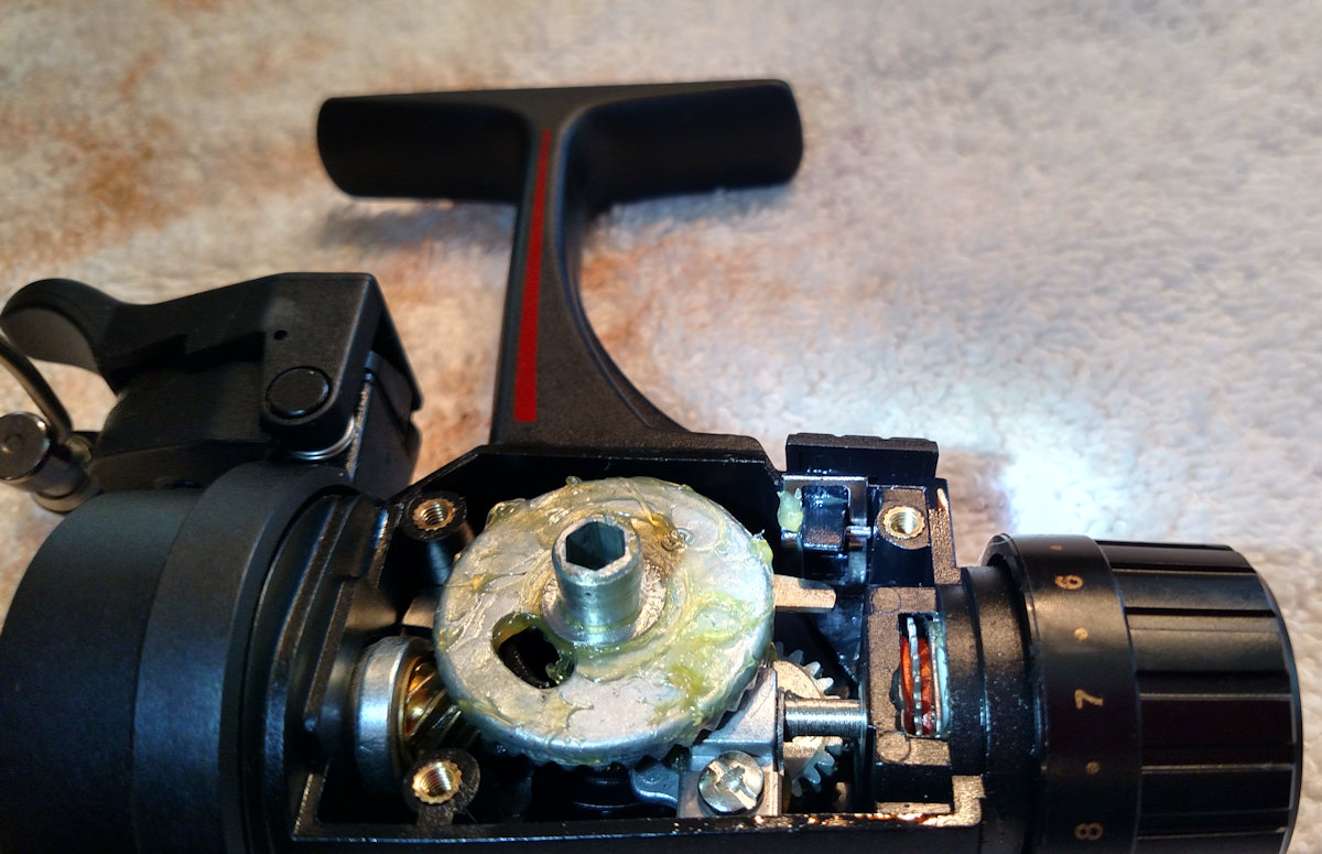
Turn the rotor until you can see the #43B block screw, then pull out the main gear and remove the screw. Now lift up the #43 crosswind arm and lift it out. The crosswind arm sits in two grooves on the #39 spool shaft, which line up on either side of the block to help secure it in place. The #43A crosswind block has a groove on the bottom which sets onto the post on the #231 crosswind gear.
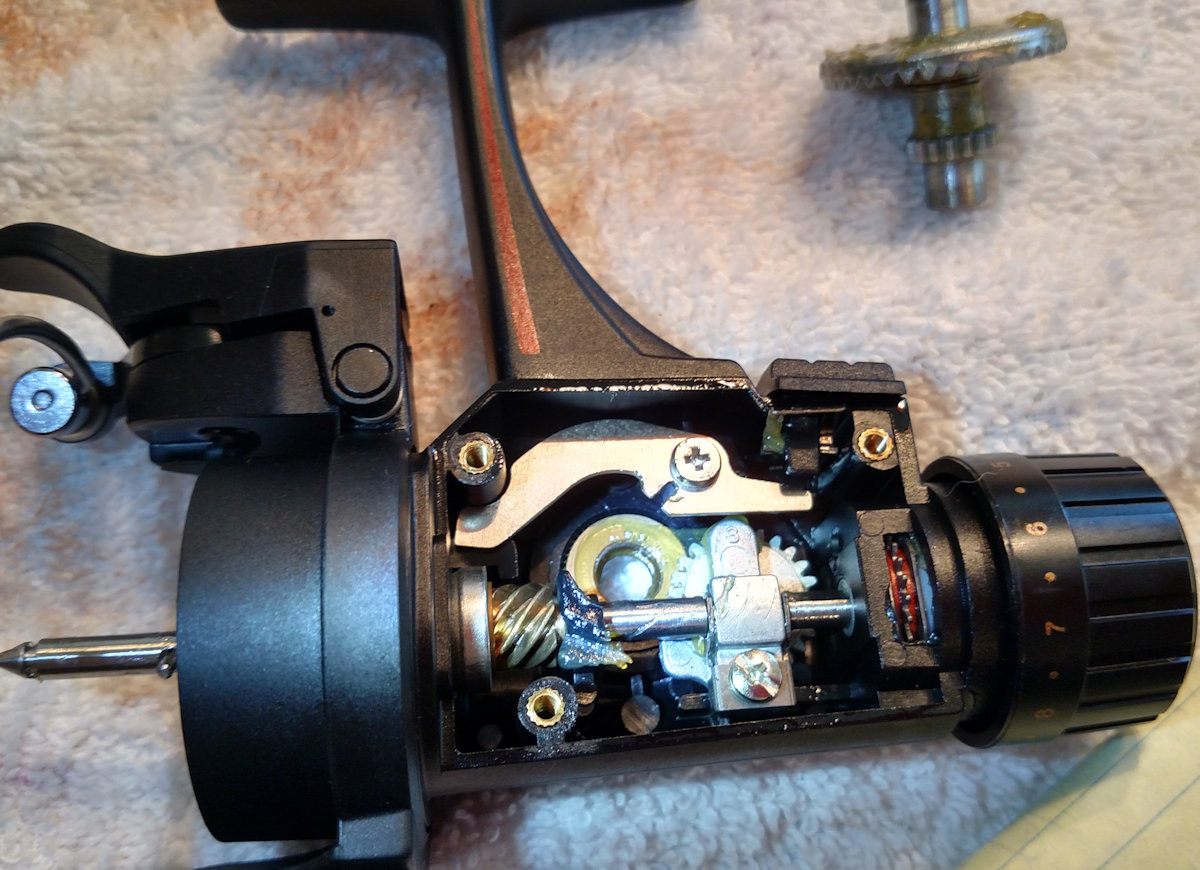
The #4 dog positioning is pretty straightforward, as it just seats into the #1 housing with the #4A dog shim underneath it and is secured by the #3 screw. I did not remove the #6E eccentric lever. It is held in place by the #6F mounting pin, with the #6D eccentric spring on it so that the bent end points towards the gears. I think you would simply use a screw driver to push the pin out if you needed to change either part.
From the factory there is minimal grease in here. Nowadays, that would be the Penn reel grease which is blue. Most greases are fine to use if you have something else, but do not use anything lithium based inside reels as it hardens up over a very short time.
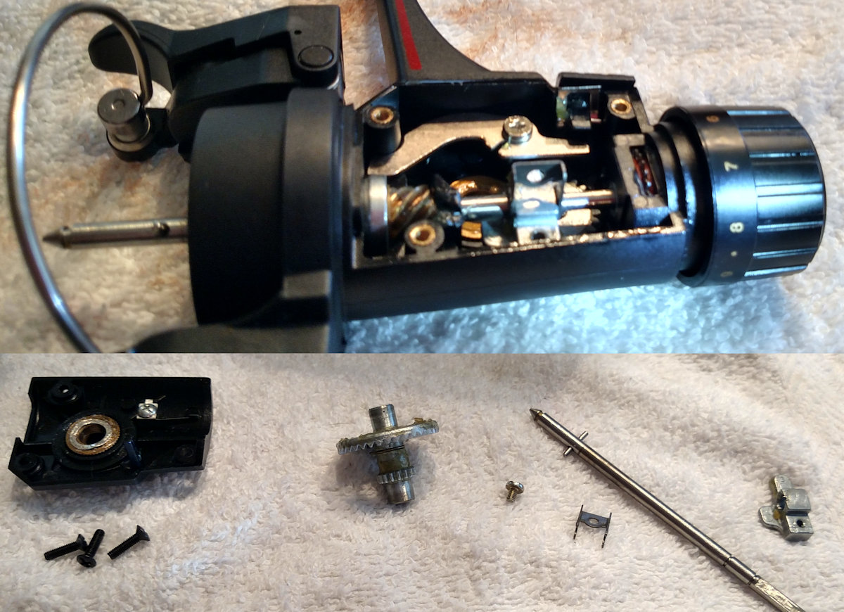
Pinion Assembly
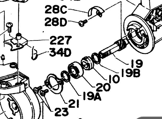
Once the #21 retainer is off, you can slide the entire pinion assembly out in one piece. Pay attention to the order and direction of the parts. For the purposes of this walk thru, I skipped taking this out. The top of the ratchet where the points are should be facing up towards the rotor, with the round end down against the frame. In the photo above you can see the position of the #28C trip cam and it's #28D mounting screw. Below is an exerpt of the assembly pieces from the schematic.
Cam and Trip Lever Positions
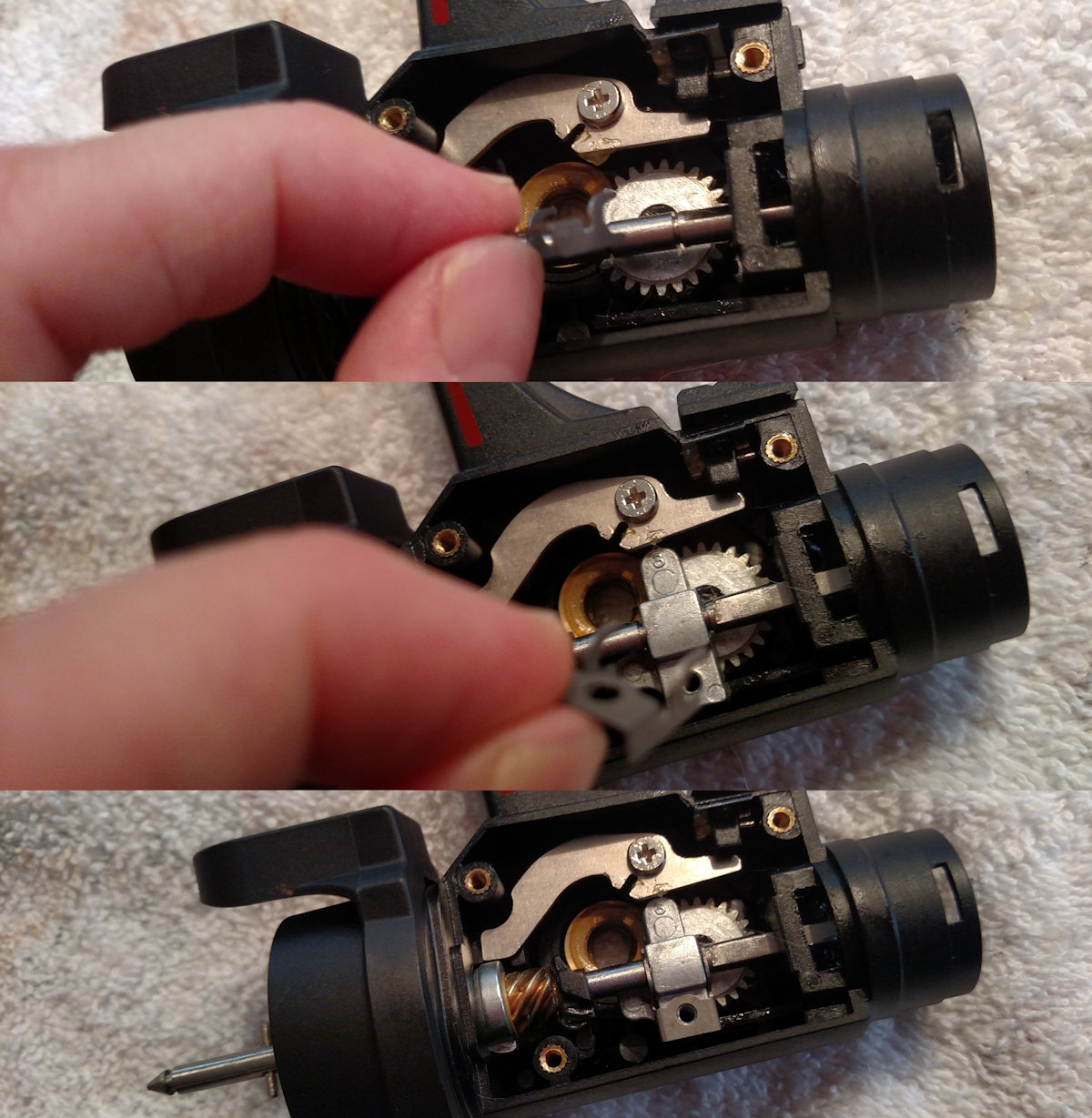
View of the underside of the rotor. Note the 19A rotor washer has stuck to it. Do not lose track of this piece. You can see the long leg of the #106 cam lever spring to the right against the wall of the rotor to provide the tension while held in place by the screw #28B. The shorter bent leg of the spring you can see is hooked around the middle of the #28A cam lever. Underneath the cam lever where you cannot see it is the #28E shim.
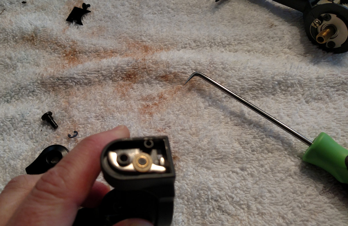
Use a bearing puller/pick to remove the c-clips. Do this carefully so that they don't fly off and disappear (and you don't impale your finger with the puller this time like I managed to do).
Continuing from underneath the rotor to the side where the cam lever interacts with the trip lever. Make sure the spring still has good tension and the tips of the levers aren't damaged. I flipped the bail over from closed to in these pics to show how they interact with each other. (Sorry, one pic came out a little blurry)
You can see the #28G washer on top of the #28 trip lever. Left image (closed bail) shows the tip of the #28A cam lever resting against the tip of the cam lever. Right (open bail) you can see how it moves over when under proper tension form the #106 spring.
Remove the #31B c-clip to slid out the # 31A bail arm pin so that you can get at the lever system. Unscrew #26A so that you can remove the #27A cover.
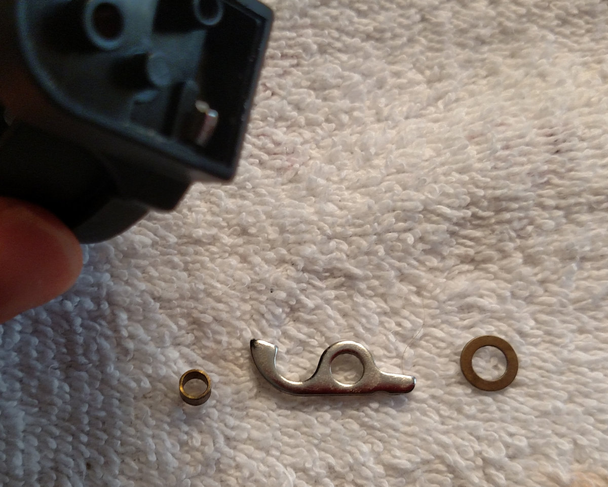
#28F Bushing that goes in the center of the #28 trip lever and the #28G washer that sits on top.
Cast Lever AKA Trigger
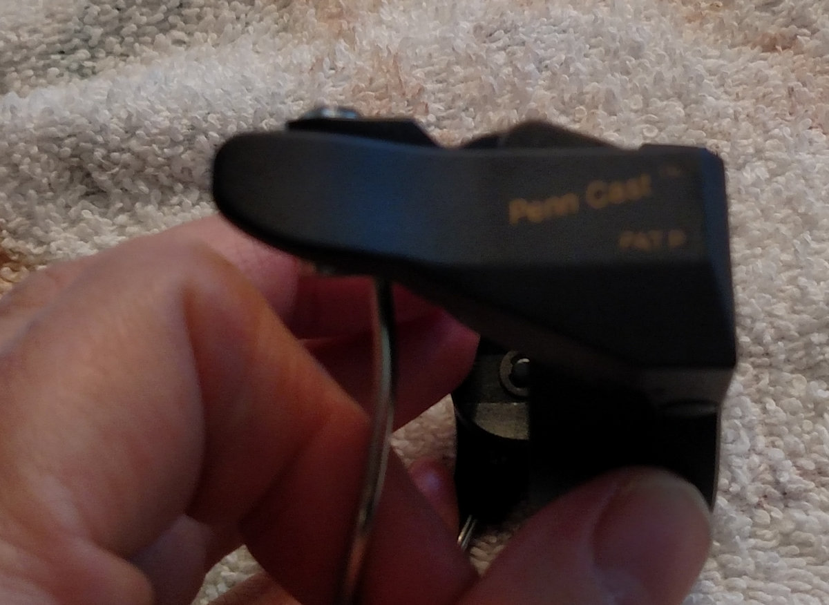
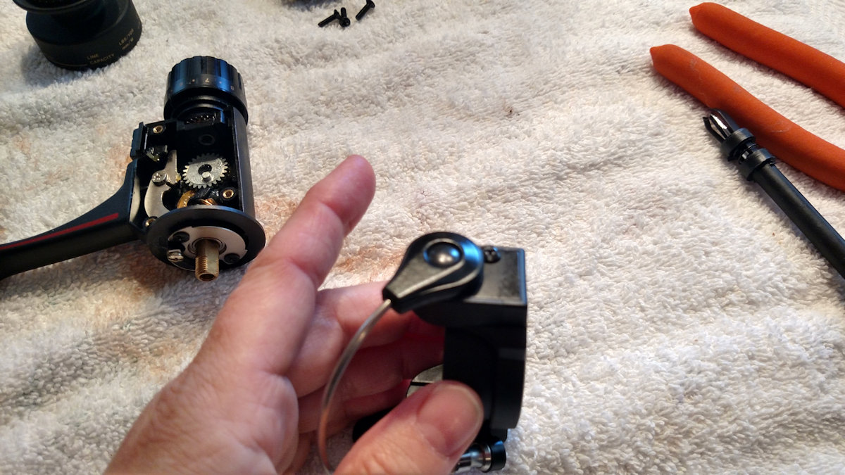
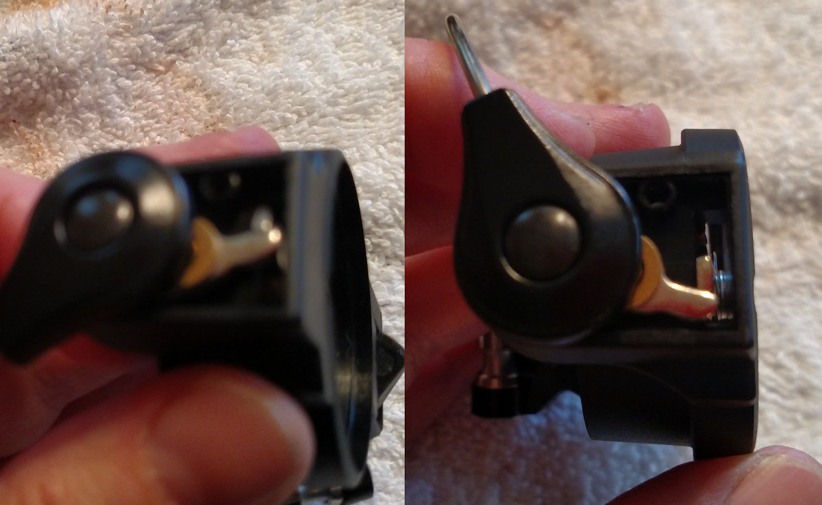
This series has a Cast Lever.
It's under tension from the #34D spring. The Cast lever allows for one-handed bail flip. You turn the handle back and the reel stops with the cast lever at the top of the rotation. You pull the lever (Pull the lever, Kronk!) and the bail flips open.
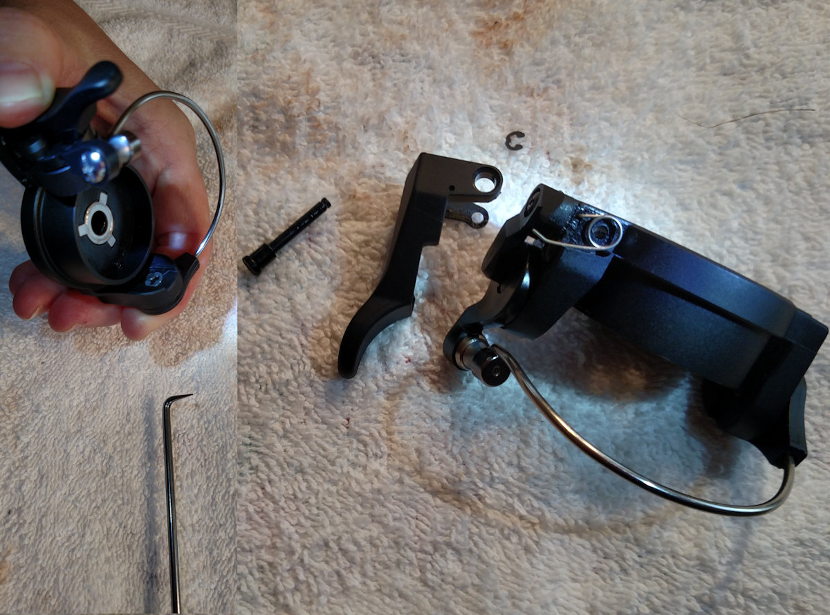
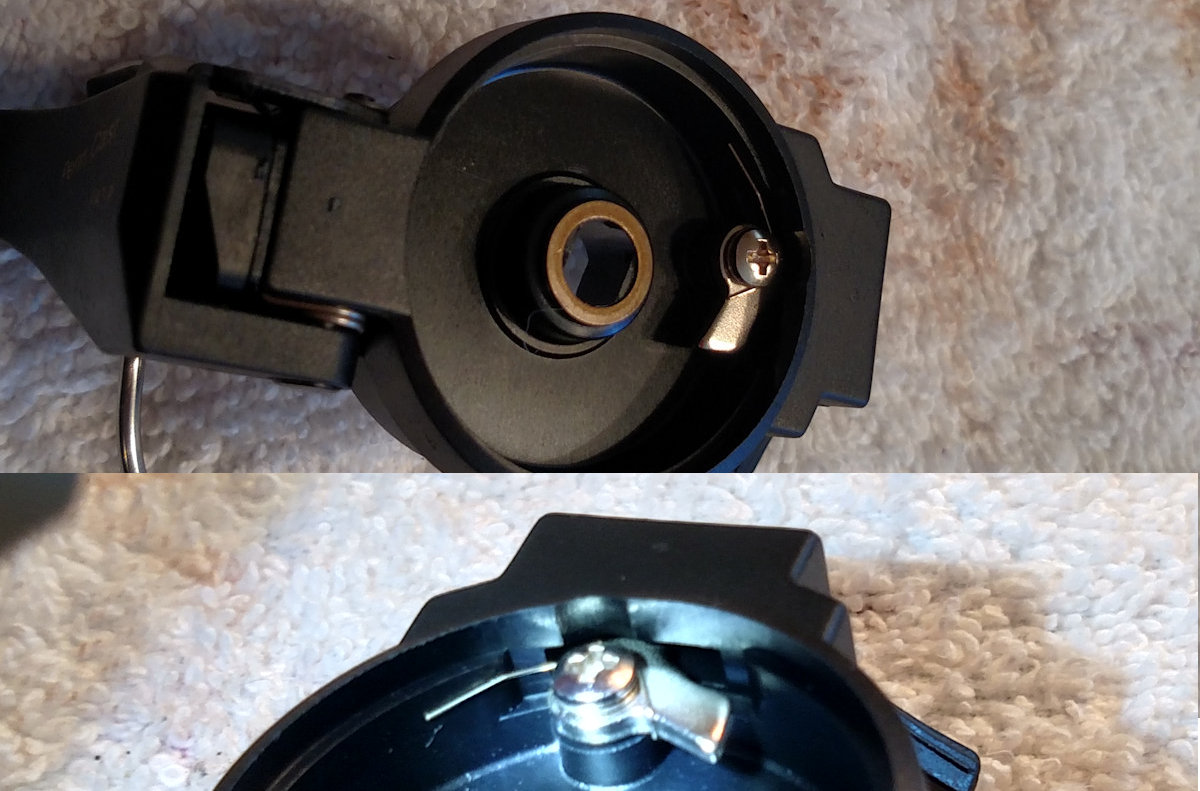
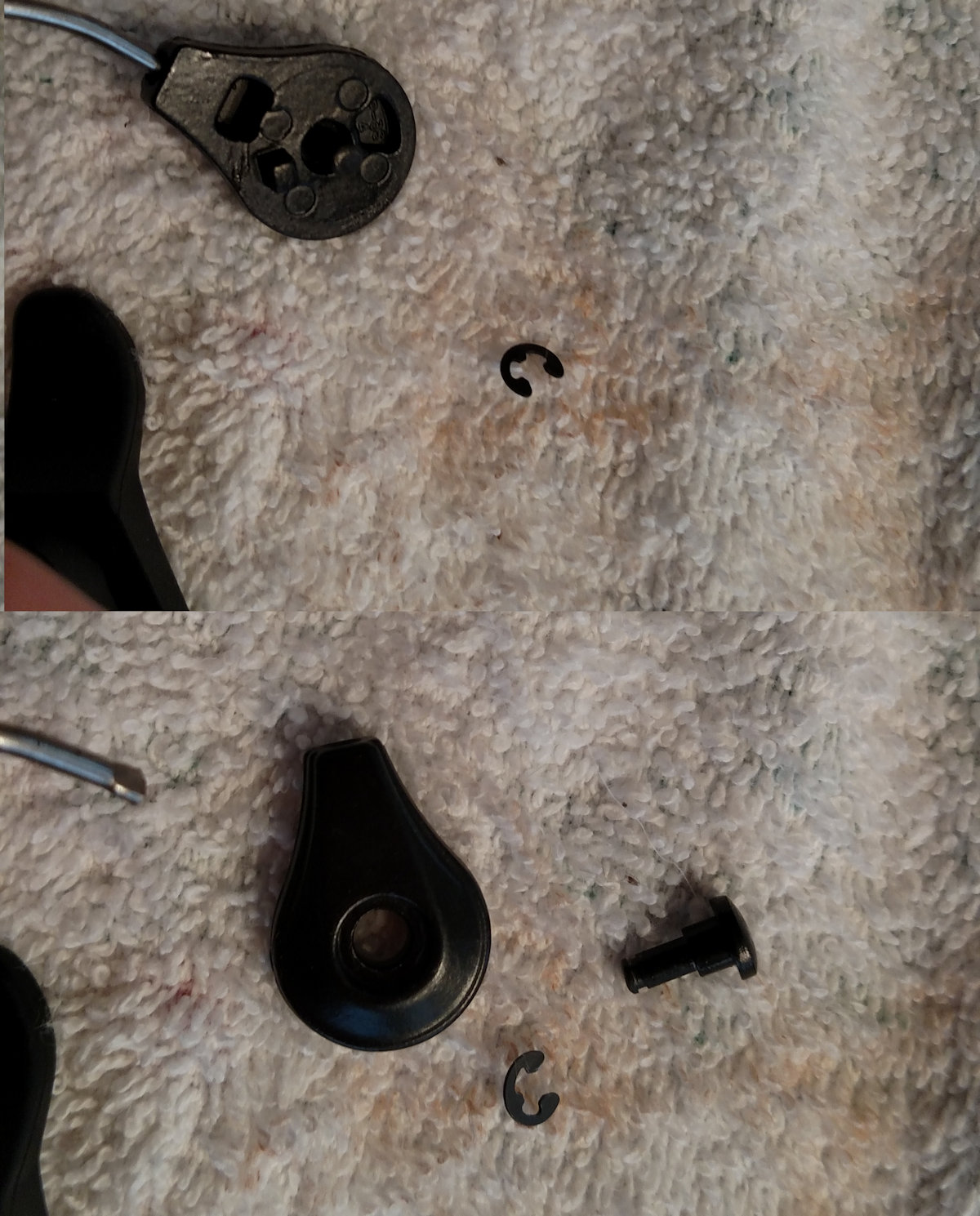
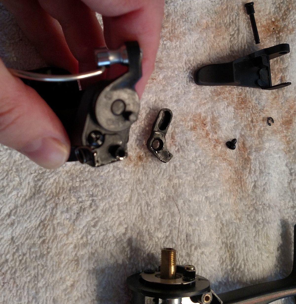
Use a bearing puller/pick to carefully remove the #34F c-clip (this is the smaller of the 3 clips on the reel) so that you can slide out the longer #34E trigger mounting pin. Carefully remove the #34C trigger so that you can see the #34D trigger spring underneath. Note how it sits here. The short bent leg is tucked into a small hole in the rotor. The long leg of the spring sits as shown.
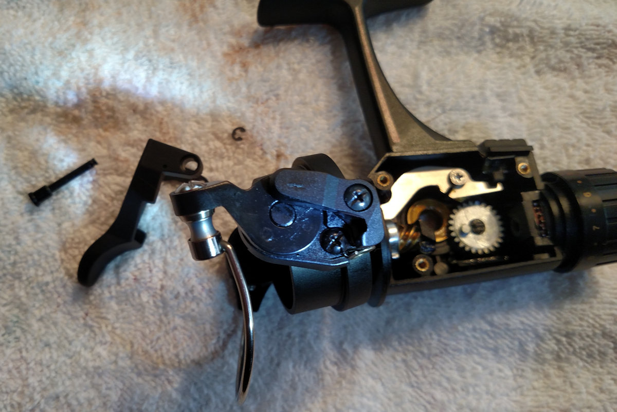
Turned so that you can se the other side where the #34A bail arm lever sits on the peg that protrudes from the #34 bail arm.
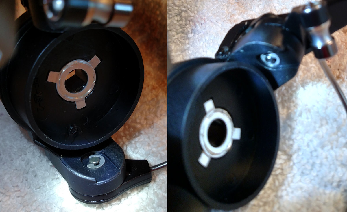
Here you can se the groove in the underside of the #34A bail arm lever which rides on that peg on the #34 bail arm.
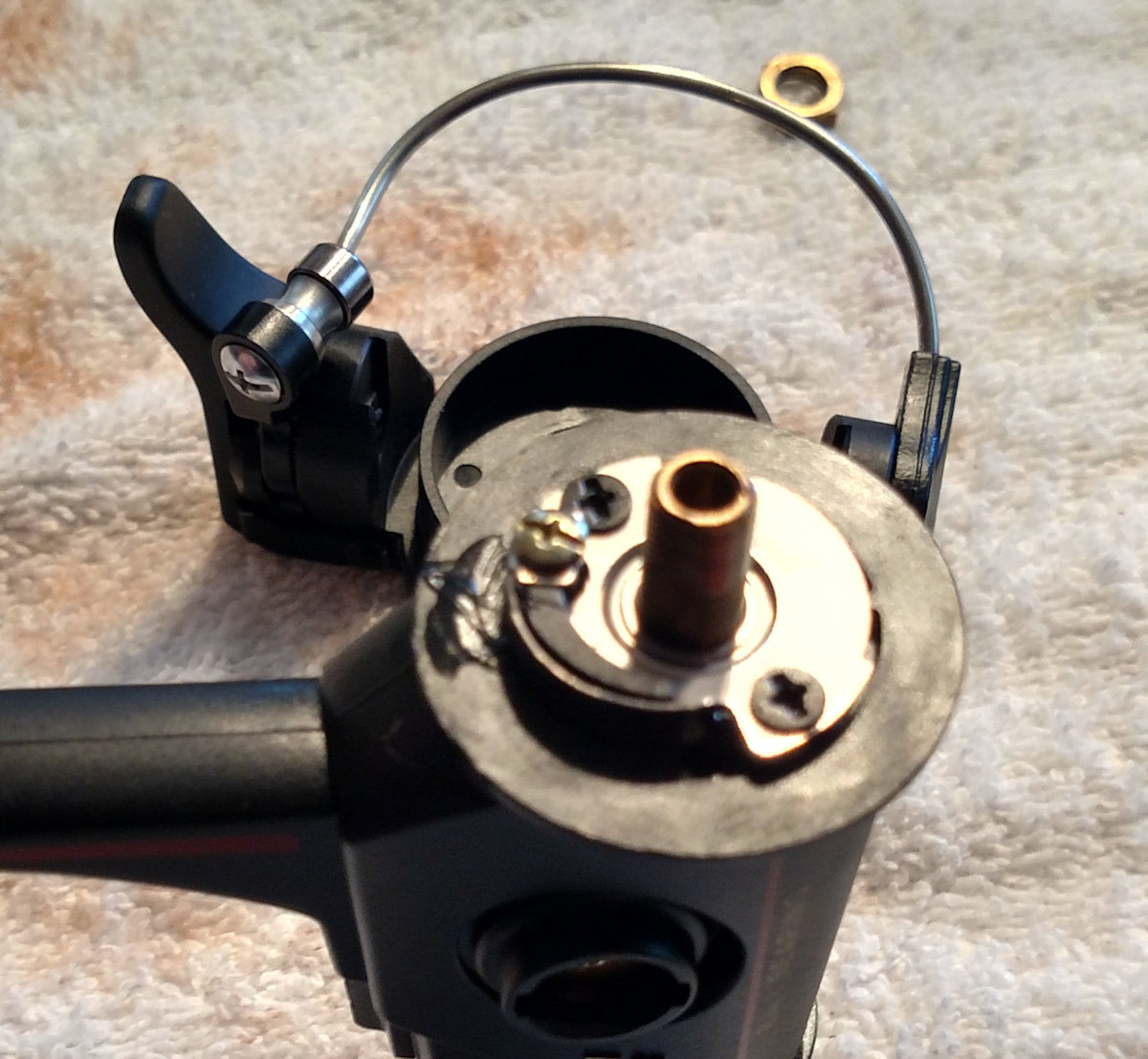
Bail Wire, Spring and Line Roller Assembly
********FORGOT PICTURE***********
forgot to take picture of the line roller parts laid out but they are fairl simple on this one. I will follow up with a pic shortly.
Okay. You've removed the #31B c-lip and slid out the #31 bail arm pin so that you can slide the bail arm out of the way to work on the bail spring. DON'T LOSE THAT TINY BUSHING! You can see it on the inside of the bail arm to the left in this photo. It may be stuck on the end of the bail spring tip..you can move it back here to the bail arm for purposes of reassembly.
Middle image in the photo above: Bail Spring: Be forwarned, once you undo the #50 screw to release the #227 bail spring cover, the #32spring MAY jump!
Right image in the photo above: Note the position of the two legs on the #32 bail spring and how it is seated inside the rotor. The small leg is bent upwards and seats inside the tiny #32A brass bushing in the bail arm.
Look for wear on the curved peg on the #34 bail arm or holes that have gone off of round if you are having a problem with the bail spring. Make sure the #32 spring itself isn't broken or bent out of shape.

Left in the above image: With the spring positioned as shown in the previous set of pictures, put the #227 cover back on and screw it down. Use a puller or screw driver to hold the spring in place against the edge of the rotor while you place the #34 bail arm with it's tiny bushing back onto the spring. It may jump, so be prepared to take the cover off again to reposition the spring.
Right side pics: Once you have the bail arm back onto the spring, hold it firmly in place and turn it over so that you can put the #34A bail arm lever back onto the peg on the other side of the bail arm. Put the #34B screw back on while still holding the bail arm firmly in place.
Reassembling the cast lever system.
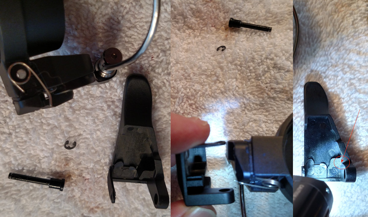
Reassembling the cast lever system. Make sure you returned the #34D trigger spring to it's correct position. Turn the rotor and carefully place the trigger back on. Note that the long end of the spring ends up tucked into the tiny notch that I have highlighted on the inside of the trigger in the far right pic of this 3 part photo.
Drag Washers - Top of the spool
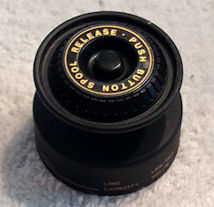
There are no drag washers in the top of this spool, so do not attempt to disassemble it.
Drag Washers - Rear Drag Assembly
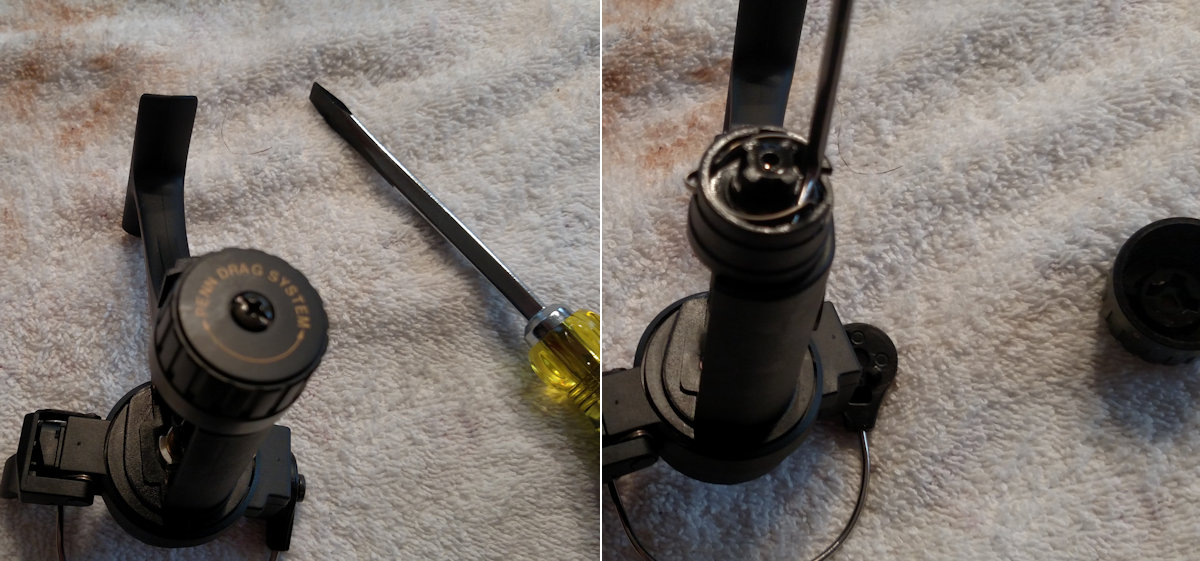
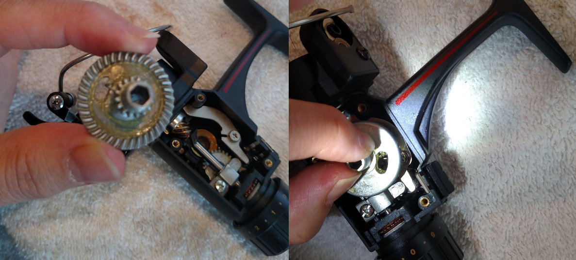
Remove the #52A screw to access the drags in the rear. Unscrew and back the #52 cap all the way off. Use a puller to loosen one of the legs of the #51 click spring to lift it out.
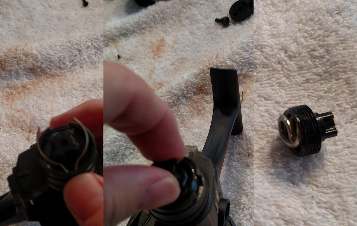
Remove the #51 click spring, then unscrew the #55 drag knob nut, which if dropped out carefully will contain the #60 thrust washer and #54 drag knob spring. Set these aside after inspection.
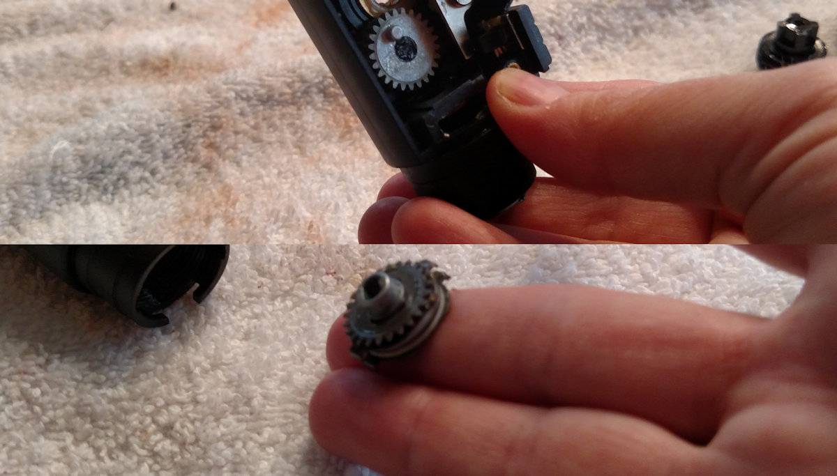
Next, put your fingers over the opening and carefully drop out the drag stack. Take note of how they are arranged. Lay them out in order and inspect for damage. You may find that one of the red #56F fibre washers may be stuck inside the housing, don't lose track of that.
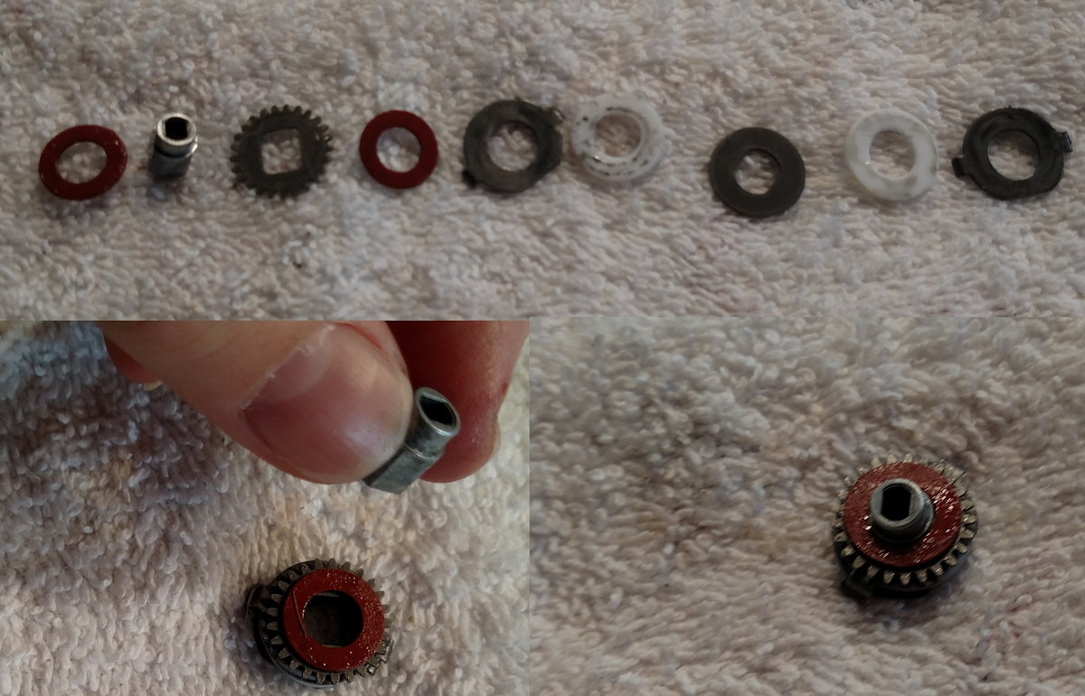
You can put the drags back in singly or reassemble the stack and try to do it all together.
I chose to do so one at a time, so the #56f went in first, then the #40 drag sleeve with the smaller end in towards the inside.
Then the rest of the stack in order, with the bent ears of the #58 earred washers pointing out towards the drag knob.
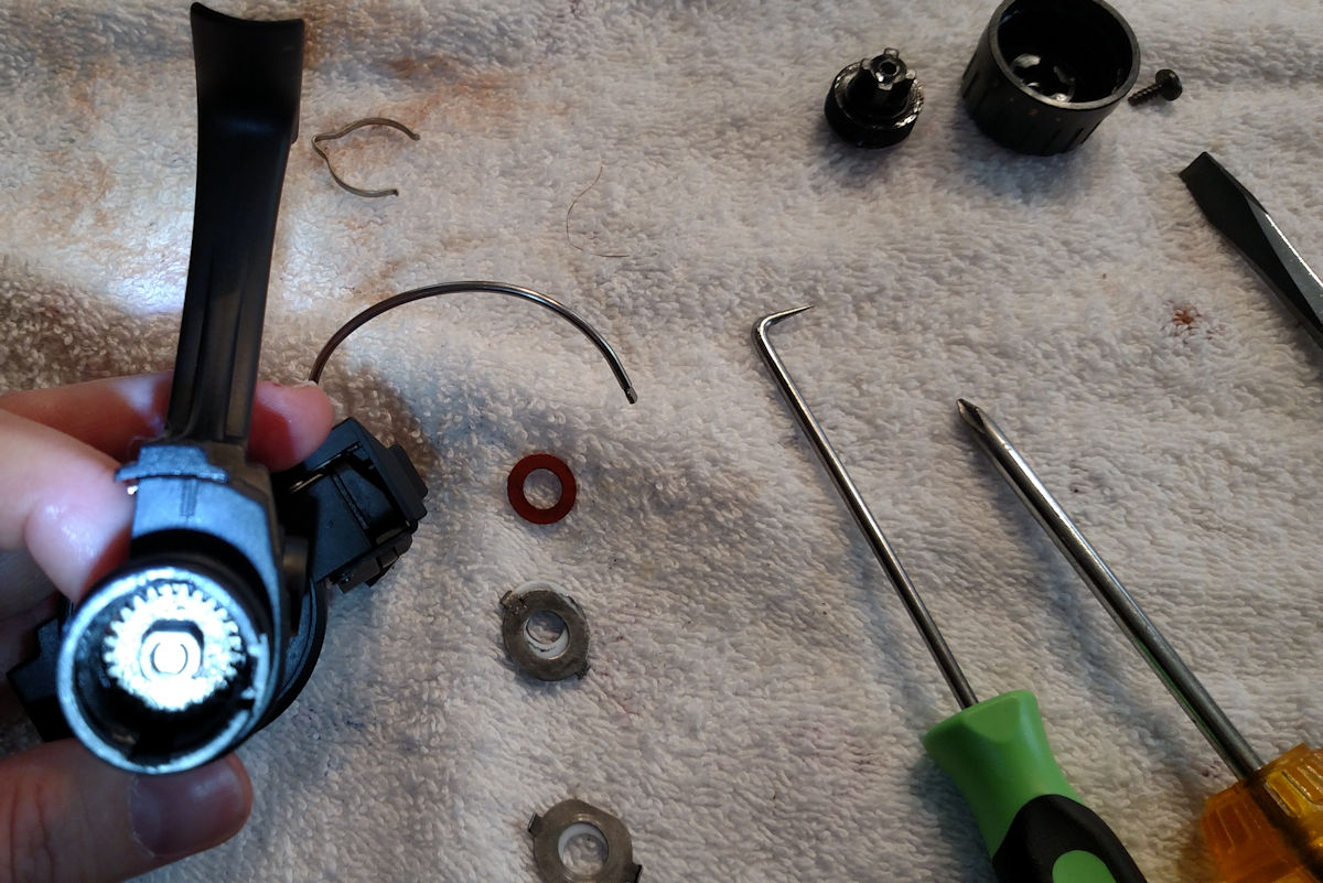
Next, put back in the #41/60/55 assembly and screw it down. Do not over tighten when assembly this or when using the rear drag as you do not want the system overcompressed.
Finally, slide the bent end of the #51 spring into it's slot and click the legs down into the housing, screw the #52 knob back on and lock it into place wiht the #52A screw.
Reassembly Spool Shaft & Block, Main Gear & Spring
Once the rear drag is back together and you have reassembled the rotor and reattached it to the pinion gear with the rotor nut, you can slide the #39 spool shaft in and resecure it. The #43 crosswind arm slides back into the two notches and the #43B screw goes back in.
Main gear positioning is made simpler by the opening in the gear. If you had to remove the spring to change it, make sure the bent end is pointing towards the second smaller set of teeth on the gear shaft, with the end of the spring visible through the hole in the gear. Then place the gear inside the reel so that the bent tip of the #5 spring seats into the slot in the #4 dog.
Order parts online for the reel(s):
https://www.mysticparts.com/PennParts/Spinning.aspx#Graphite
0 Comments